A&A 379, 697-707 (2001)
DOI: 10.1051/0004-6361:20011293
C. Aime - R. Soummer - A. Ferrari
UMR 6525 Astrophysique, Faculté des Sciences, Université de Nice Sophia Antipolis, Parc Valrose, 06108 Nice Cedex 2, France
Received 17 July 2001 / Accepted 20 August 2001
Abstract
We describe the principle of an apodization technique for rectangular apertures that can be implemented
using a Michelson or a Mach-Zender interferometer. Using several interferometers, any integer power of cosine
functions can be obtained. The technique is considered for application to the Apodized Square Aperture (ASA)
concept recently proposed by Nisenson & Papaliolios (2001). Simple analytic expressions for the Point Spread
Functions of such apodized apertures are given. For a cosine to the power N apodization, the resulting focal
plane amplitude is simply the sum of N+1 weighted and shifted sine cardinal functions. The interest of such
apodized apertures for coronagraphy is investigated. It appears that these apodization functions are very
efficient provided that only a central part of the cosine-arch is used. Analytic expressions are derived for the
residual amplitude left in an image of the aperture after the coronagraphic experiment. Best results are obtained
with a cosine squared apodization.
Key words: instrumentation: high angular resolution - techniques: interferometric - techniques: high angular resolution - telescopes - stars: planetary systems
One of the most ambitious objectives of present astronomy is the direct detection of an Earth-like planet orbiting
a nearby star, and the spectral analysis of its atmosphere to search for life. At first sight, the required angular
resolution is not that great: seen at 10 parsec, the angular separation between Earth and Sun is 0.1 arcsec. There
are about 100 to 200 target stars (F, G, K, M) within that distance (TPF Science Working Group 1999). The main difficulties come from the
brightness ratio between the planet and its parent star. This ratio, of the order of 109 in the visible,
presents its most favorable value of about 106 in the infrared near ![]() m. The infrared range of wavelength
is also favorable for the detection of molecular absorption bands such as
m. The infrared range of wavelength
is also favorable for the detection of molecular absorption bands such as
![]() ,
,
![]() and
and
![]() (Léger et al. 1999).
(Léger et al. 1999).
The received flux from a planet located at 3 or 4 Airy discs from the star is about 103 to 106 times fainter than the average level of star-diffracted light and the photon noise will prevent the direct observation of the planet in realistic observing times.
Several techniques have been recently studied to cancel as best possible the star diffracted light (Roddier & Roddier 1997; Gay & Rabbia 1996; Baudoz et al. 2000a,2000b; Abe et al. 2001; Rouan et al. 2000). They can be roughly classified in three groups of methods, one referring to Nulling interferometry (Bracewell 1978; Mennesson & Mariotti 1997; Angel & Woolf 1997), the second to direct imaging using coronagraphy and the last to apodization (Nisenson & Papaliolios 2001). Nulling interferometry has lead to the Darwin project (Leger 1993; Leger et al. 1996), while coronagraphic techniques are presently under study for TPF (TPF Science Working Group 1999; Guyon & Roddier 2000; Boccaletti et al. 2000; Pedretti et al. 2000; Aime et al. 2001).
Coronagraphy, invented by Lyot (1930; Lyot 1939) for the observation of the solar corona, is the first recognized
technique to provide direct imaging capabilities of exoplanets (Bonneau et al. 1975; Malbet 1996; Watson et al. 1991). The technique has been
recently improved by the use of a ![]() Phase Mask (PM) instead of the Lyot's opaque mask. (Roddier & Roddier 1997; Guyon et al. 1999). To
obtain the required reduction factors necessary for telluric planet detection, coronagraphy must be coupled with
an apodization of the entrance aperture. In that case, reduction factors as large as 107 have been reported for
the monochromatic case (Guyon & Roddier 2000). This gain is obtained at the expense of a small loss of transmission.
Phase Mask (PM) instead of the Lyot's opaque mask. (Roddier & Roddier 1997; Guyon et al. 1999). To
obtain the required reduction factors necessary for telluric planet detection, coronagraphy must be coupled with
an apodization of the entrance aperture. In that case, reduction factors as large as 107 have been reported for
the monochromatic case (Guyon & Roddier 2000). This gain is obtained at the expense of a small loss of transmission.
Recently, Nisenson & Papaliolios (2001) proposed the alternative concept of Apodized Square Aperture (ASA), based on the elegant
idea introduced by Watson et al. (1991) to take advantage of the rapid drop of the diffracted light along the diagonal
direction for a square aperture. Provided that the adequate apodizer is realized, these authors have shown that an
ASA can reach the required dynamic range for planet detection without coronagraphy. They describe transmission
apertures with several shapes of apodizations (sonine, cosine, or squared cosine) for which the overall
transmission factors are of the order of ![]() .
.
The work proposed in this paper originates from the search of an apodization method based on an interference process which may be more effective than the classical one using amplitude transmission masks. Its principle and possible optical implementation are given in Sect. 2. The method makes it possible to obtain any power of cosine apodizations such as the ones considered for the ASA concept. For these apodizations, we give in Sect. 3 the analytical expressions for the PSF observed at the focus of the telescope.
The same kind of cosine apodization is analyzed for its use in stellar coronagraphy in Sect. 4: the cosine shape appears to be very efficient, provided that only a fraction of the cosine arch is used (larger for Lyot's mask than for R&R's mask). Section 5 examines the chromatic effets of the technique. Conclusion are given in Sect. 6. As we shall see, the proposed interferometric apodization technique appears to be a versatile solution.
The purpose of apodization is to obtain a redistribution of the energy in the diffraction pattern, reducing the energy in the wings of the PSF. In Signal Processing, the problem has been extensively studied for the spectral analysis of temporal signals (Papoulis 1981; Harris 1978). In Optics, this effect can be obtained with appropriate modifications of the pupil function. A large review of apodization techniques was made by Jacquinot & Roizen-Dossier (1964). These authors also suggested to illuminate the pupil with an interference pattern in a spectroscopic system for better slit illumination, but they abandoned the idea. We reconsider this idea herein and give below the principle of the technique.
For the ASA concept, and more generally for an apodized rectangular aperture, the pupil transmission and its corresponding focal plane diffraction can be written as separate functions of x and y. This property can be used to describe the technique for a one-dimensional telescope. The generalization to a two-dimensional rectangular or square aperture is straightforward.
In the focal plane, the normalized monochromatic amplitude impulse response ![]() is proportional to its
Fourier transform:
0pt
is proportional to its
Fourier transform:
0pt
| (1) |
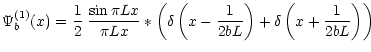
The proposed apodization technique is very simple. Let us assume that by some means, we are able to split this
amplitude ![]() into two identical waves and shift one of them by
into two identical waves and shift one of them by
![]() .
The minima of the first wave
then correspond to the maxima of the second and provided that we maintain the coherence, we obtain the addition of
the two amplitudes. Outside the central part of the PSF, positive and negative values approximately cancel each
other (Fig. 1). The amplitude of the wings of the PSF is then reduced with, of course, the drawback
of an enlarged central peak.
.
The minima of the first wave
then correspond to the maxima of the second and provided that we maintain the coherence, we obtain the addition of
the two amplitudes. Outside the central part of the PSF, positive and negative values approximately cancel each
other (Fig. 1). The amplitude of the wings of the PSF is then reduced with, of course, the drawback
of an enlarged central peak.
![\begin{figure}
\par\includegraphics[width=8.8cm,clip]{MS1697f1.eps} \end{figure}](/articles/aa/full/2001/44/aa1697/img16.gif) |
Figure 1: Illustration of the apodization technique in the focal plane. Top left: unapodized amplitude split into two shifted amplitude (bottom left). The result of this coherent addition is the first-apodized amplitude (top center). This approach can be iteratively reproduced: the split and shifted amplitudes (bottom center) and second-apodized amplitude (top right). |
| Open with DEXTER | |
The resulting amplitude remains oscillatory with the same distance 1/L between zeros. We can iteratively reproduce this approach: several identical optical systems can be used successively to produce the shifts and obtain the different degrees of apodization. The procedure is schematized in Fig. 1.
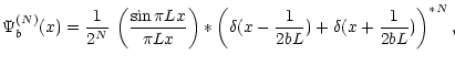
These successive apodizations can be considered as a direct superposition of several shifted amplitudes with appropriate coefficients. The second-order apodization is equivalent to the addition of three shifted amplitudes with coefficients (1, 2, 1). The third apodization is a four-amplitude addition, with coefficients (1, 3, 3, 1). It can be easily shown from the illustration that the amplitude coefficients are given by Pascal's triangle (Fig. 2).
| |
Figure 2: Illustration of the amplitude coefficients for successive apodizations. The encircled numbers corresponds to the amplitude coefficients. The first apodization corresponds to a 2 beam interference, the second apodization to a 3 beam interference with coefficients 1, 2, 1 for the amplitude. Amplitude coefficients are given by Pascal's Triangle. |
| Open with DEXTER | |
A shift of the two identical amplitudes in the focal plane corresponds to a slight tilt of the wavefronts at the pupil plane. This is equivalent to considering localized fringes of equal thickness on the pupil.
This can be easily achieved with an interferometer by division of amplitude, such as the Michelson or the Mach-Zendher interferometer, setting images of the entrance aperture on the interferometer mirrors of the interferometer and slightly tilting a mirror to introduce a thin wedge-shaped film.
The required shift of the focal amplitude corresponds to an optical path difference of ![]() at the edges of
the pupil (destructive interference): the center of the pupil must be bright and the pupil edges dark. The main
drawback of a Michelson interferometer is that half of the flux is lost backwards to the source. However, it can
be used for an easy laboratory test experiment, which will be reported in a future work. A better solution seems
to use a Mach-Zendher interferometer, which has two outputs.
at the edges of
the pupil (destructive interference): the center of the pupil must be bright and the pupil edges dark. The main
drawback of a Michelson interferometer is that half of the flux is lost backwards to the source. However, it can
be used for an easy laboratory test experiment, which will be reported in a future work. A better solution seems
to use a Mach-Zendher interferometer, which has two outputs.
Obtaining two apodized pupils with a Mach-Zendher interferometer appears to be impossible for conservation of
energy reasons. The relative phase shift between the reflected and transmitted beams in a thin or symmetric
beam-splitter is ![]() ;
this imposes complementary fringes at the two outputs of the interferometer. Thus we
can obtain an apodized output (with same transmission as a perfect classical apodizer) and an "anti-apodized"
output which pupil amplitude is brighter at the edges and leads to the opposite effect to apodization. This output
cannot directly be used for planet detection, but remains usable for other purposes, such as tracking.
;
this imposes complementary fringes at the two outputs of the interferometer. Thus we
can obtain an apodized output (with same transmission as a perfect classical apodizer) and an "anti-apodized"
output which pupil amplitude is brighter at the edges and leads to the opposite effect to apodization. This output
cannot directly be used for planet detection, but remains usable for other purposes, such as tracking.
The successive apodizations can be produced with several successive interferometers, but with the problem of multiplying optical surfaces. An unique multiple-beam, specifically designed interferometer may also be possible and has to be studied. Mach-Zendher interferometers made of two glass blocks associated together with total internal reflections may be preferred to mirrors to preserve a high throughput and minimize the number of optical surfaces. However, for coronagraphy, classical interferometers with mirrors would permit the user to tune the wedge fringes for practical optimization, as we shall see later.
Of course, the main drawback of such an interferometric technique is its chromatism. This point will be discussed
in Sect. 5. For an actual two-dimensional aperture and if the apodization is required in two dimensions, the use of
two interferometers at an orientation of ![]() will be needed.
will be needed.
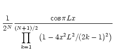
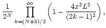
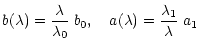
In this section, we show that the apodization functions obtained with the interferometric technique correspond to the cosine to the power of N apodizer and calculate the analytical expressions of the PSF for these apodization functions. For more generality and later use, we consider the case where the shift may be b times smaller than the optimal 1/L considered in the previous section.
The amplitude corresponding to the addition of two PSF images distant one another of
![]() can be
written as:
can be
written as:
 |
(4) |
 |
(6) |
![\begin{figure}
\par\includegraphics[width=5.8cm,clip]{MS1697f3.eps} %
\end{figure}](/articles/aa/full/2001/44/aa1697/img40.gif) |
Figure 3: From top to bottom: unapodized PSF, and successive order of N given in Table 1. Dashed plots corresponds to a cut of the PSF along the diagonal direction, as considered in the ASA Concept. |
| Open with DEXTER | |
| Apodization | Impulse responses (normalized) |
| unapodized: |
|
1st order, b=1 |
|
2nd order, b=1 |
|
3rd order, b=1 |
|
The corresponding amplitude in the pupil plane can be obtained directly as the Fourier transform of
Eq. (5). Using basic properties of the Fourier transform of a convolution product, we obtain the
simple expression:
The proposed interferometric technique may be a solution to produce these apodization functions for the ASA concept. To obtain the two dimensional apodizer, two successive devices must be successively used in orthogonal directions. Making b larger than one corresponds to the use of a partial cosine arch apodization: only the central part is used. This apodization will be of interest for coronagraphy (Sect. 4). The above expressions for the amplitude impulse response can be used for an analytical study of the ASA concept even if the interferometric technique is not used to produce the aperture transmission: the diffracted light intensity along the diagonal for a square aperture is simply written as the fourth power of the amplitudes given in Eqs. (7), (8) and Table 1. Illustrations of the diagonal diffracted light for the ASA are given in Fig. 3. These curves were already numerically given by Nisenson & Papaliolios (2001).
The purpose of coronagraphy is to reduce the star diffracted light in the whole field to provide direct
imaging capabilities of faint sources in the vicinity of the star. For the sake of clarity,
we briefly recall some fundamental aspects of this otherwise very well-known technique.
In Lyot's coronagraphy (Lyot 1930) applied to exoplanet detection, an opaque mask is set at the center of the stellar image. According
to Babinet's theorem, the diffraction pattern of this dark mask appears in negative amplitude on an image of the
entrance-pupil. There, a diaphragm (Lyot's stop) is set to get rid of the light diffracted outside the telescope
aperture image. Inside this diaphragm, direct and diffracted light of the star are interfering destructively,
while the light coming from the planet remains almost unaffected. However, because the smooth diffraction pattern
of the mask cannot fit the flat impinging wavefront, the starlight is not fully cancelled. Typically, an integrated reduction
factor of the order of 10-3 may be obtained using an optimized Lyot mask for a square aperture.
The technique was improved by Roddier & Roddier (1997) and Guyon et al. (1999), replacing the opaque mask by a ![]() Phase Mask (PM): the
performance can be enhanced while the principle remains the same.
Phase Mask (PM): the
performance can be enhanced while the principle remains the same.
Most of the star residual light appears at the edges of the pupil in the relay pupil plane. In the
original technique, the Lyot's stop diameter is smaller than the pupil size to reduce this effect. A classical improved solution is
to use optimized entrance pupil apodization. We examine here the effect of the apodized apertures permitted by
the technique proposed in the previous section.
![\begin{figure}
\par\includegraphics[width=9cm,clip]{MS1697f4.eps} \end{figure}](/articles/aa/full/2001/44/aa1697/img47.gif) |
Figure 4: Residual energy as a function of the mask size a and apodization parameter b for a square aperture. The value b=1 corresponds to full cosine apodization (Sect. 2). Higher values of b correspond to a partial apodization. For Lyot's coronagraphy several minima are obtained for different a and b values. See Table 2 for numerical values. |
| Open with DEXTER | |
| Technique | Apodization | Mask size: | Residual energy | Apodizer intensity transmission |
| parameter: b | (square aperture) | (square aperture) | ||
| R&R, |
2.160 | 0.848 |
|
70% |
| R&R, |
2.995 | 0.848 |
|
70% |
| Lyot, |
1.103 | 2.147 |
|
30% |
| Lyot, |
1.254 | 2.621 |
|
22% |
| Lyot 2nd min. (N=1) | 1.056 | 4.040 |
|
30% |
| Lyot 2nd min. (N=2) | 1.154 | 4.468 |
|
19% |
| ASA |
1 | 25% | ||
| ASA |
1 | 14% |
For a rectangular aperture of size
![]() ,
the coronagraphic mask must be a rectangle of size
,
the coronagraphic mask must be a rectangle of size
![]() proportional to the inverse of the aperture. Following the approach of Guyon & Roddier (2000) and Aime et al. (2001), the
residual amplitude within the entrance aperture left by the coronagraphic process can be written as:
proportional to the inverse of the aperture. Following the approach of Guyon & Roddier (2000) and Aime et al. (2001), the
residual amplitude within the entrance aperture left by the coronagraphic process can be written as:
The case for entrance pupil apodization combined with coronagraphy appears clearly in Eq. (10):
the idea is to optimize the pupil shape to achieve the best amplitude subtraction for the on-axis unresolved
star. In other words we shall try to solve the equation
![]() within the aperture.
within the aperture.
This solution can be approached very closely by using an iterative numerical algorithm as first proposed by
Guyon & Roddier (2000): iterations are computed between the entrance and exit pupil planes, and the residual amplitude is
negatively re-injected in the entrance pupil. The apodization functions so obtained do not resemble to the full
cosine apodized aperture (b=1), but are very similar to the central part of a cosine arch.
![\begin{figure}
\par\includegraphics[width=8.8cm,clip]{MS1697f5.eps}\end{figure}](/articles/aa/full/2001/44/aa1697/img67.gif) |
Figure 5: Slices of the energy for different values of apodization parameter b (full lines correspond to the optimal b of Table 2). |
| Open with DEXTER | |
We recently noticed that there is a formal solution to this problem (Aime et al. 2001, submitted) and that the cosine arch is indeed a very good approximation to a perfect apodization. In any case, as we shall see below, it permits the aperture to give very good stellar light rejection.
We consider here a square aperture for which ax=ay=a and bx=by=b. A simple optimization criterion to test the efficiency of the coronagraphic experiment is to consider the integrated residual energy within the exit pupil, for the unresolved on-axis star. Note that since coronagraphy is a direct imaging technique, this criterion is rather pessimistic. Using minimisation techniques, the optimal mask size a and apodization parameter b can be numerically computed. The results are given in Table 2 for a square aperture, and a few details on the computations are given in Appendix B.
It may be also interesting to represent the variations of this energy as a two dimensional function of a and b. This is done in Fig. 4, for a square aperture, and may be more visible in Fig. 5 where slices of the functions of Fig. 4 are given.
Lyot's and R&R's techniques have quite different behaviours: there is a single well-defined global minimum for the PM technique, whereas successive several local minima exist for Lyot's coronagraphy as the mask size increases. The optimal b value is different if the solution is searched at the first or second minimum. This means that for a given shape of apodization, there is an optimal mask size, and is reciprocally so. The second optimal value gives a much better extinction ratio, at the expense of a reduced capability of detecting a planet very close to the star (larger a). These effects are visible in Figs. 4, 5 and in Table 2.
Since most of the residual light is concentrated at the edges of the exit pupil, even with entrance pupil
apodization, we can take advantage of the initial Lyot's method and use a smaller exit pupil than the entrance
pupil. We have empirically tested a few Lyot's stop reductions
![]() .
The optimization results are
different when carried out with a reduced Lyot's stop and can provide a better extinction inside the reduced exit
pupil. However, a detailed study of the Signal to Noise Ratio (SNR) would be needed to determine the optimum exit
pupil reduction.
.
The optimization results are
different when carried out with a reduced Lyot's stop and can provide a better extinction inside the reduced exit
pupil. However, a detailed study of the Signal to Noise Ratio (SNR) would be needed to determine the optimum exit
pupil reduction.
A representation of the residual intensities
![]() of Eq. (10) is given in Fig. 6
for the optimal values of a and b. The residual field intensity (RFI) for the optimal cosine apodizations
with coronography are illustrated in Fig. 7. These RFI expressions are not analytic and have been computed
numerically. The results, summarized in Table 2, lead to the following comments:
of Eq. (10) is given in Fig. 6
for the optimal values of a and b. The residual field intensity (RFI) for the optimal cosine apodizations
with coronography are illustrated in Fig. 7. These RFI expressions are not analytic and have been computed
numerically. The results, summarized in Table 2, lead to the following comments:
Lyot's technique is however much less efficient than R&R's one in terms of resolution since the pupil mask is much larger. However the technique may have interesting aspects: it is much simpler, and performances of the coronagraph are not very sensitive to the preciseness of a. Lyot's technique might eventually be used at the second minimum leading of course to a higher rejection, comparable to that obtained with a PM with cosine apodization, but the capability of detecting a close-by planet is about 5 times worse than for the R&R technique.
A PSF for the planet can be computed if we assume that the coronagraphic mask (Lyot's mask or R&R's phase mask)
has almost no effect on the re-imaged planet whatever its position in the field. For that we can use
Eq. (2) and Eq. (3) i.e. the sum of two or three shifted sine cardinal functions. An
illustration is given in Fig. 9. Note that here the smaller the PSF, the better the result, since the
detection of the planet will be made with less background noise.
![\begin{figure}
\par\includegraphics[width=12cm,clip]{MS1697f6.eps}\end{figure}](/articles/aa/full/2001/44/aa1697/img74.gif) |
Figure 6: Top: entrance apodized pupils (amplitude transmission). Bottom: residual intensity in the exit pupil plane. From left to right: R&R with cosine, R&R with cosine squared, Lyot with cosine, Lyot with cosine squared. |
| Open with DEXTER | |
The interferometric technique we have described in Sect. 2 to obtain the cosine apodizations is wavelength sensitive.
Since the size of the diffraction pattern in the focal plane increases with the wavelength, shifts and mask sizes
should vary accordingly. If not, and such is the case that we analyse here, the parameters a and b are only
optimized for a single wavelength ![]() within the bandwidth.
within the bandwidth.
The computations made previously can be used to compute chromatic effects. For that, we simply assume that at a
wavelength ![]() we are using inappropriate
we are using inappropriate
![]() and
and
![]() values of the form:
values of the form:
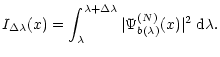
For pure apodization, the resulting PSF is obtained integrating
![]() of Eq. (5)
within the spectral window:
of Eq. (5)
within the spectral window:
![\begin{figure}
\par\includegraphics[width=6.8cm,clip]{MS1697f7.eps}\par\end{figure}](/articles/aa/full/2001/44/aa1697/img82.gif) |
Figure 7: Residual Field Intensity in the final focal plane for a one-dimensional aperture. Top: PSF for a raw aperture without apodization nor coronagraphy (full line), Lyot's coronagraphy with a cosine apodizer (dash-dotted). Lyot's coronagraphy with a cosine squared apodizer (dotted). R&R's coronagraphy with a cosine apodizer (long-dashed)). Bottom: Lyot's coronagraphy is plotted at the second minimum (see Table 2 for the corresponding parameters). |
| Open with DEXTER | |
A solution to the chromatic problem would be to use an achromatization lens-system which produces a magnification
of the focal image proportional to ![]() over the bandpass. These kind of achromatizers have been
successfully tested for pupil plane interferometry (Wynne 1979; Roddier et al. 1980). In that case, the image of the planet
will appear as a dispersed spectrum. For very wide bandwiths, such an achromatization technique would probably
fail and a separation into several bands is certainly needed to adapt the achromatization in each band.
over the bandpass. These kind of achromatizers have been
successfully tested for pupil plane interferometry (Wynne 1979; Roddier et al. 1980). In that case, the image of the planet
will appear as a dispersed spectrum. For very wide bandwiths, such an achromatization technique would probably
fail and a separation into several bands is certainly needed to adapt the achromatization in each band.
On the other hand, classical apodizers using absorbing devices also present technological challenges to realize the exact transmission function. The physical absorption process is wavelength dependent, and chromatic problems may also occur; multilayers may be needed to obtain an achromatic transmission over a wide bandpass. With the interferometric technique, the apodization function (cosine, cosine squared) is physically produced by the interference phenomenon itself and may be exactly obtained.
For PM coronagraphy, the first difficulty is to obtain a wavelength independent ![]() phase mask. Assuming that
this result is obtained, we can compute the effect relative to the variation of the parameters a and b within
the spectral bandwidth. Curves of Fig. 4 can be used for that: the residual intensity is the result of
the integration along the parametric curve defined by equations
phase mask. Assuming that
this result is obtained, we can compute the effect relative to the variation of the parameters a and b within
the spectral bandwidth. Curves of Fig. 4 can be used for that: the residual intensity is the result of
the integration along the parametric curve defined by equations
![]() and
and
![]() of Eq. (12).
Examples are given in Fig. 11, for the one-dimensional case, where we consider that a perfect
of Eq. (12).
Examples are given in Fig. 11, for the one-dimensional case, where we consider that a perfect ![]() phase mask is used.
phase mask is used.
The chromatic effect on the mask size is much more sensitive in the R&R case than in Lyot's case. This can be
understood easily from Fig. 5. R&R's coronagraphy may give even worse results than Lyot if the
chromatic effect on the mask size is not corrected. On the contrary, R&R coronagraphy is not very sensitive
concerning the chromatism of the apodization, because the optimal apodization function corresponds to a very weak
apodization (partial cosine arch)
![\begin{figure}
\par\includegraphics[width=9cm,clip]{MS1697f8.eps}\end{figure}](/articles/aa/full/2001/44/aa1697/img84.gif) |
Figure 8: Residual intensity of the star in the focal plane for the 4 considered techniques: Top left: Lyot's coronagraphy with cosine apodization (at first minimum). Top right: Lyot's coronagraphy with cosine squared apodization (at first minimum). Bottom Left: R&R's PM with cosine apodization. Bottom right: R&R's PM with cosine squared apodization. |
| Open with DEXTER | |
![\begin{figure}
\par\includegraphics[width=8.8cm,clip]{MS1697f9.eps}\end{figure}](/articles/aa/full/2001/44/aa1697/img85.gif) |
Figure 9: PSF for the planet (the effect of coronagraphy on the off-axis planet is assumed to be negligible), PSF for R&R with a cosine apodization (full line), PSF for R&R with a cosine squared apodization (long dash), PSF for Lyot with a cosine apodization (dashed line), PSF for Lyot with a cosine square apodization (dotted line) |
| Open with DEXTER | |
![\begin{figure}
\par\includegraphics[width=6.8cm,clip]{MS1697f10.eps} \end{figure}](/articles/aa/full/2001/44/aa1697/img86.gif) |
Figure 10:
Effect of increasing bandwidth on the PSF for the interferometric apodization (N=1) and (N=2): achromatic PSF, effect of a |
| Open with DEXTER | |
![\begin{figure}
\par\includegraphics[width=7cm,clip]{MS1697f11.eps} \end{figure}](/articles/aa/full/2001/44/aa1697/img87.gif) |
Figure 11:
Residual energy as a function of the bandwithexpressed in percents (this computation is made for
the one-dimensional case). Top: effect of mask size chromatism andinterferometric apodization chromatism. R&R is much more sensitive to the mask size and can be worse than Lyot for a bandwidth over |
| Open with DEXTER | |
The technique is then studied for application to the ASA concept recently proposed by Nisenson & Papaliolios (2001). Our approach allowed us to give a simple analytic expression for the cosine diffraction patterns considered by these authors. For a cosine to the power N apodization, the resulting focal plane amplitude is simply written as the sum of N+1weighted and shifted sine cardinal functions. The weights are given by Pascal's triangle. The shifts must be equal to 1/L (L being the length of the aperture in units of wavelenth) for a full cosine-arch apodized-aperture (maximum at the center and zero at the edges). In that case, very simple analytical expressions can be worked out. Making the shifts b times smaller, one obtains a partially apodized aperture (central part 1/b of the cosine-arch).
We have then analyzed the effects of apodizations on coronagraphy. Here also we have been able to derive analytic
expressions for the residual amplitude left in an image of the aperture after the coronagraphic experiment.
We found that the full apodized aperture (b=1) is not suitable for coronagraphy. On the other hand, very good results
can be obtained with partial cosine apodizations. For R&R's phase mask technique a rejection of
![]() is obtained using a simple cosine apodization with b=2.160, and a rejection of
is obtained using a simple cosine apodization with b=2.160, and a rejection of
![]() is obtained using a cosine squared apodization with b=2.995.
is obtained using a cosine squared apodization with b=2.995.
The computation was made for a square aperture, but it could also apply to a rectangular aperture. For Lyot's technique, the cosine apodization is not very good, and a cosine squared is needed (10-5 rejection with b=1.254).
It was beyond the scope of this paper to give the relative factors of merit of the ASA technique to the Lyot and R&R phase mask coronagraphic techniques; a major point will probably be the technical possibility of realization of each of them. The behavior depends also on the distance of the planet to the star, coronagraphic techniques being more effective for very close objects. If this distance is large, the disparities between the techniques is reduced. The proposed interferometric apodization technique appears to be versatile and can be adjusted to produce the partial or full cosine arch apodizations required by these techniques. The effect of its chromatism is not too severe for a reasonable bandwidth.
The residual amplitude left in the entrance aperture by the coronagraphic process (Eq. (10)) depends on
the function
![]() (Eq. (11)) which describes the diffraction pattern of the
coronagraphic mask.
(Eq. (11)) which describes the diffraction pattern of the
coronagraphic mask.
![$\displaystyle F\left(x\right)=
\frac{-1}{2\pi} \left(\frac{\sin(\pi x)}{b L} \left(-{\rm Ci}[A]+{\rm Ci}[B]+{\rm Ci}[C]-{\rm Ci}[D]\right) \right.$](/articles/aa/full/2001/44/aa1697/img93.gif) |
|||
![$\displaystyle \left. + \frac{\cos(\pi x)}{b L}\left(-{\rm Si}[A]-{\rm Si}[B] +{\rm Si}[C]+{\rm Si}[D]\right)\right)$](/articles/aa/full/2001/44/aa1697/img94.gif) |
(A.2) |
![$\displaystyle F\left(x\right)=
\frac{-1}{4\pi} \left(\frac{\sin(2\pi x)}{b L}\left(-{\rm Ci}[A]+{\rm Ci}[B]+{\rm Ci}[C]-{\rm Ci}[D]\right)\right.$](/articles/aa/full/2001/44/aa1697/img100.gif) |
|||
![$\displaystyle \left.+ \frac{\cos(2\pi x)}{b L}\left({\rm Si}[A]+{\rm Si}[B]+{\r...
... \left({\rm Si}[a \pi (\frac{L}{2} - x)]+{\rm Si}[a \pi
(\frac{L}{2}+x)]\right)$](/articles/aa/full/2001/44/aa1697/img101.gif) |
(A.3) |
The computations have been carried out analytically as far as possible and we have used the software Mathematica (Wolfram 1999). However, some of the results have been obtained numerically.
Acknowledgements
The authors would like to thank François Martin for his very helpful contribution to the preliminary laboratory tests of the interferometric apodization technique. Thanks are also due to François-Xavier Schmider for interesting discussions.

![$\displaystyle F\left(x\right)=\frac{1}{\pi} \left( {\rm Si} \left[ \pi a\left(x...
...\right) \right] -{\rm Si}\left[\pi a \left(x-\frac{L}{2}\right)\right]\right) .$](/articles/aa/full/2001/44/aa1697/img91.gif)