MAXIM will offer major advances in the X-ray band and is technically so challenging that it may seem premature to consider how comparable resolution might be obtained at still higher energies, where performance is currently far inferior to that possible at lower energies. But this paper aims to show that this may be feasible and that, although there are some disadvantages of working at higher energies, in other respects things actually become simpler.
Fresnel Zone Plates (FZPs, Fig. 1a),
as invented by Soret (1875), are in some respects related
to the Laue lens mentioned in Sect. 2
as each small region of an FZP can be thought of as a
small grating that diffracts the incoming radiation towards the
focus, the pitch of the diffraction grating becoming smaller as
higher deflection angles are needed at larger radii.
![\begin{figure}
\par\resizebox{6cm}{!}{\includegraphics[angle=-90,clip]{MS1333f1.eps}}
\end{figure}](/articles/aa/full/2001/32/aa1333/img10.gif) |
Figure 1: a) A Fresnel Zone Plate (FZP), b) A Phase Zone Plate (PZP), c) A Phase Fresnel Lens (PFL). |
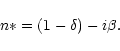
A simple FZP has a maximum efficiency of
![]() .
This results from the
fact that apart from the first order (n=1) focus,
energy also passes unfocussed (n=0), to higher orders
.
This results from the
fact that apart from the first order (n=1) focus,
energy also passes unfocussed (n=0), to higher orders
![]() and to virtual focii
and to virtual focii
![]() .
.
![\begin{figure}
\par\resizebox{8.6cm}{!}{\includegraphics[clip]{MS1333f2.eps}}\end{figure}](/articles/aa/full/2001/32/aa1333/img14.gif) |
Figure 2:
The thickness, |
As well as independently proposing the FZP, Rayleigh pointed out the
possibility, demonstrated by Wood (1898), of obviating the zero
order loss in what can be termed the Phase Zone Plate (PZP, Fig. 1b). The opaque regions are replaced by ones that allow
the radiation to pass, but which have a thickness of refractive
material such as to impose a phase shift of ![]() .
The theoretical
efficiency limit is raised to
.
The theoretical
efficiency limit is raised to
![]() .
.
Ideally the thickness, and hence the phase change, within each zone should be a continuous function of radius. This leads to the kineform, or Phase Fresnel Lens (PFL) (Miyamoto 1959) (Fig. 1c), in which ideally all of the power is directed into order n=1, giving an efficiency of up to 100%. The same effect can be achieved with a graded refractive index instead of varying thickness (Fujisaki & Nakagiri 1990; Yang 1993). Stepped approximations to a PFL (di Fabrizio & Gentili 1999) can still have efficiencies approaching this value. Effectively the graded diffraction grating is blazed using refraction to concentrate all of the power into order n=1.
FZPs, PZPs and PFLs are increasing being used for X-ray microscopy and other applications at electron synchrotron facilities. Some example parameters for lenses that are based on these principles and that have been used for laboratory applications are given in Table 1.
In view of the need for high efficiency, we will concentrate here on PFLs,
and hence the refractive index of the material from which the lens
is made is a critical parameter.
The refractive index of a material at X-ray/gamma-ray energies is
usually expressed as
 |
(1) |
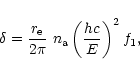 |
(2) |
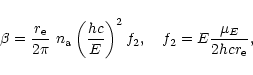 |
(3) |
Well above absorption edges, and apart from small
relativistic and nuclear corrections, f1 is essentially constant
and equal to the number of electrons per atom, Z. It follows
that the thickness ![]() necessary to
provide a phase shift of
necessary to
provide a phase shift of ![]() is approximately proportional to energy.
The thickness of a PZP or the mean thickness of a PFL will be
equal to
is approximately proportional to energy.
The thickness of a PZP or the mean thickness of a PFL will be
equal to ![]() .
Values of
.
Values of ![]() for some example materials are
shown in Fig. 2. Much of the present work
depends on the fact that as one moves up in
energy from the X-ray band, although
for some example materials are
shown in Fig. 2. Much of the present work
depends on the fact that as one moves up in
energy from the X-ray band, although ![]() increases, the
associated absorption
becomes smaller and over a wide range of energy the losses fall to a
low level (Fig. 2).
increases, the
associated absorption
becomes smaller and over a wide range of energy the losses fall to a
low level (Fig. 2).
| Example reported laboratory systems | Example diffractive lens | |||||
| Reference | (a) | (b) | (c) | telescopes | ||
| Energy (keV) | 0.4 | 8, 20 | 8 | 200 | 500 | 847 |
| Type | FZP | PZP | Stepped PFL | PFL | ||
| Material | Ge | Au | Ni | Al | ||
| Maximum thickness, t ( |
0.18 | 1.6, 3 | 4.5 | 450 | 1200 | 1900 |
| Shortest period, p ( |
0.06 | 0.5 | 2 | 2500 | 1000 | 590 |
| Aspect ratio (t/p) | 3 | 3.2, 6 | 2.25 | 0.5 | 1.2 | 2.0 |
| Focal length f (m) |
|
3, 7.5 | 1 | 109 | ||
| Diameter (d) (mm) | 0.08 | 0.19 | 0.15 | 5000 | ||
| f-number
|
1 | 1600, 4000 | 6700 |
|
||
| Theoretical diffraction-limited | ||||||
| resolution: Spatial ( |
0.035 | 0.3 | 1.2 | |||
| Angular (arc sec) |
|
|
|
|||
References: (a) Spector et al. (1999) (b) Chen et al. (1999) (c) di Fabrizio & Gentili (1999).
The focal length, f, the finest pitch of the pattern, p, and the lens diameter, d, are inter-related; we review first some of the considerations which dictate the choice of these parameters.
For microscopy, very fine pitch patterns are sought because the
diffraction limited spatial resolution in the object plane is
![]() .
Here the resolution is that given by the Rayleigh critereon,
which corresponds to the 60% power diameter.
.
Here the resolution is that given by the Rayleigh critereon,
which corresponds to the 60% power diameter.
For astronomy, the diffraction limited
image spot size is equal to ![]() ,
as given by the above expressions, but
it is the angular resolution
,
as given by the above expressions, but
it is the angular resolution
![]() that is important.
From the points of view of the angular resolution of a telescope
and of flux concentration, there is no reason to make p much
smaller than the detector spatial resolution.
Considerations of electron scattering
and stopping distance suggest that the detector
spatial resolution is likely to be limited to about 1 mm at 1 MeV,
scaling approximately as E0.8.
that is important.
From the points of view of the angular resolution of a telescope
and of flux concentration, there is no reason to make p much
smaller than the detector spatial resolution.
Considerations of electron scattering
and stopping distance suggest that the detector
spatial resolution is likely to be limited to about 1 mm at 1 MeV,
scaling approximately as E0.8.
Pitches finer than the detector resolution may nevertheless
sometimes be useful. They may allow larger lenses
or shorter focal length to be used because
the finest pitch dictates the maximium diffraction angle and hence relates
f and d:
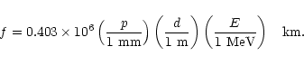 |
(4) |
Copyright ESO 2001