A&A 373, 345-358 (2001)
DOI: 10.1051/0004-6361:20010538
PLANCK LFI: Comparison between Galaxy Straylight Contamination and other
systematic effects
C. Burigana1
- D. Maino2
- K. M. Górski3,4 - N. Mandolesi1
- M. Bersanelli5
- F. Villa1
- L. Valenziano1
- B. D. Wandelt6 - M. Maltoni7
- E. Hivon8,9
1 -
Istituto TeSRE, Consiglio Nazionale delle Ricerche, via Gobetti 101, 40129 Bologna, Italy
2 -
Oss. Astr. Trieste, via G.B. Tiepolo 11, 34131 Trieste, Italy
3 -
ESO, European Southern Observatory, Karl-Schwarzschild Str. 2, 85748 Garching, Germany
4 -
Warsaw University Observatory, Warsaw, Poland
5 -
Dipartimento di Fisica, Università di Milano, and IFC/CNR, via Celoria 16, 20133 Milano, Italy
6 -
Department of Physics, Princeton University, Princeton, NJ 08544, USA
7 -
Instituto de Física Corpuscular - CSIC/UVEG, Edificio Institutos de Paterna, Apt. 22085, 46071 Valencia, Spain
8 -
Observational Cosmology, California Institute of Technology, MS 59-33, CA 91125 Pasadena, USA
9 -
IPAC, California Institute of Technology, MS 100-22, CA 91125 Pasadena, USA
Received 2 October 2000 / Accepted 14 March 2001
Abstract
The straylight contamination due to the Galactic emission
(GSC, Galaxy Straylight Contamination)
entering at large angles from the antenna centre direction
may be one of the
most critical sources of systematic effects in observations
of the cosmic microwave background (CMB) anisotropies
by future satellite missions such as PLANCK and MAP.
While future accurate measurements of the real antenna pattern are
necessary for a firm evaluation of this effect, on the basis of the currently
available optical simulations we are able to produce simulated data
useful for the development of data analysis methods and the optimization
of the optical design.
For the Low Frequency Instrument (LFI),
the GSC is expected to be particularly crucial
at the lowest frequency channels.
We describe here different methods to evaluate the impact of this effect
and compare it with other systematics of instrumental and astrophysical origin.
The results are presented in terms of simulated data streams and
maps, Fourier series decomposition and angular power spectrum.
The contributions within a
few degrees from the beam centre dominate
the GSC near the Galaxy plane.
The antenna sidelobes at intermediate and large angles
from the beam centre
dominate the GSC at medium and high Galactic latitudes.
We find a GSC peak at  15
15  K and a GSC
angular power spectrum above that of the white noise for multipoles
K and a GSC
angular power spectrum above that of the white noise for multipoles
 ,
albeit smaller than that of CMB anisotropies by a factor
larger than 10.
At large multipoles,
the GSC affects the determination of CMB angular power spectrum
significantly less than other kinds of instrumental
systematics, such as main beam distortions and 1/f noise.
Although the GSC is largest at low
Galactic latitudes, the contamination
produced by far pattern features at medium and
high Galactic latitudes, peaking at 4 K,
has to be carefully investigated,
because the combination of low amplitude of Galaxy emission in those regions
with the extremely good nominal PLANCK sensitivity
naturally makes high Galactic latitude areas the targets for
unprecedentedly precise estimation of cosmological CMB anisotropy.
This paper is based on PLANCK LFI activities.
,
albeit smaller than that of CMB anisotropies by a factor
larger than 10.
At large multipoles,
the GSC affects the determination of CMB angular power spectrum
significantly less than other kinds of instrumental
systematics, such as main beam distortions and 1/f noise.
Although the GSC is largest at low
Galactic latitudes, the contamination
produced by far pattern features at medium and
high Galactic latitudes, peaking at 4 K,
has to be carefully investigated,
because the combination of low amplitude of Galaxy emission in those regions
with the extremely good nominal PLANCK sensitivity
naturally makes high Galactic latitude areas the targets for
unprecedentedly precise estimation of cosmological CMB anisotropy.
This paper is based on PLANCK LFI activities.
Key words: cosmology: cosmic microwave background - Galaxy: general - space vehicles -
telescopes - methods: data analysis
After the great success of COBE-DMR
(Smoot et al. 1992; Bennett et al. 1996a; Górski et al. 1996)
which probed the gravitational instability scenario
for structure formation through the detection of CMB anisotropies
at scales of few degrees,
and the recent balloon-borne experiments
at high sensitivity and
resolution on limited sky regions
(De Bernardis et al. 2000; Hanany et al. 2000),
supporting a universe model with
 (Lange et al. 2000; Balbi et al. 2000; Jaffe et al. 2000),
ultimately, future progress of the CMB anisotropy cosmology will be based on
two space missions, MAP (Microwave Anisotropy Probe)
(see Bennett et al. 1996b) by NASA
and PLANCK
by ESA, planned to be launched respectively in the years
2001 and 2007.
(Lange et al. 2000; Balbi et al. 2000; Jaffe et al. 2000),
ultimately, future progress of the CMB anisotropy cosmology will be based on
two space missions, MAP (Microwave Anisotropy Probe)
(see Bennett et al. 1996b) by NASA
and PLANCK
by ESA, planned to be launched respectively in the years
2001 and 2007.
In particular, the Low Frequency Instrument (LFI, Mandolesi et al. 1998) and
the High Frequency Instrument (HFI, Puget et al. 1998) on-board PLANCK
will cover together a wide frequency range (30 900 GHz) which
should significantly improve the accuracy of the subtraction
of foreground contamination from the primordial CMB anisotropy,
providing at the same time a gold-mine
of cosmological as well as astrophysical information (see, e.g., De Zotti et al. 1999a
and references therein).
900 GHz) which
should significantly improve the accuracy of the subtraction
of foreground contamination from the primordial CMB anisotropy,
providing at the same time a gold-mine
of cosmological as well as astrophysical information (see, e.g., De Zotti et al. 1999a
and references therein).
To fully reach these scientific goals,
great attention has to be devoted
to properly reducing and/or subtracting all the possible systematic effects.
Detailed simulation codes have been developed and are continuously
implemented to analyse the impact of several classes of instrumental effects
related to the
behaviour of the optics, instruments and environment
for a wide set of possible scanning strategies
(see, e.g., Burigana et al. 1998; Delabrouille 1998; Maino et al. 1999;
Mandolesi et al. 2000a). Ultimately this effort leads to the optimization
of the mission design and the production of realistic
data streams and simulated maps for data analysis tools as well as
a realistic definition of PLANCK's scientific performance.
In particular,
the behaviour of the PLANCK antenna patterns, both at intermediate
and large angles from the directions of beam centres, have to be carefully considered.
The requirement for the rejection of unwanted radiation coming from directions far
from the optical axis (straylight) is stringent for PLANCK and
does not pertain only to the telescope itself, but to the
entire optical system, including also solar panels, shielding,
thermal stability and focal assembly components.
The primary sources of error for the LFI are those due to
imperfect off-axis rejection by the optical system of radiation
from the Sun, Earth, Moon, planets, Galaxy and the spacecraft itself
(de Maagt et al. 1998).
The variations of the spurious straylight signal during the mission
introduce contaminations in the anisotropy measurements.
The antenna response features at large angular scales from the beam centre
(far sidelobes) are determined largely by
diffraction and scattering from the edges of the mirrors and from nearby
supporting structures. Therefore they can be reduced by decreasing the illumination at
the edge of the primary, i.e. increasing the edge taper,
defined as the ratio of the power per unit area
incident on the centre of the mirror to that incident on the edge.
Of course, the higher the edge taper, the lower the sidelobe level
and the straylight contamination.
On the other hand, increasing the edge taper
has a negative impact on the angular resolution
for the fixed size of the primary mirror (see, e.g., Mandolesi et al. 2000a).
A trade off between angular resolution and straylight contamination
has to be found.
The main aim of this work is to evaluate the impact of
the Galactic emission as a source of straylight for PLANCK LFI.
We will then compare it with the effects generated by
other kinds of systematics,
the main beam distortion introduced by optical aberrations and the 1/f noise
related to gain fluctuations in LFI radiometers,
and with the astrophysical contamination from
the Galaxy and the extragalactic sources in the main beam.
At LFI frequencies,
the Galaxy straylight contamination (GSC)
is expected to be particularly crucial
at the lowest frequencies, due to the increase of synchrotron absolute
emission and anisotropies with the wavelength.
For simplicity, we limit our analysis
to the case of the 30 GHz channel, but the methods presented here
can be extended to higher frequencies.
In Sect. 2 we briefly describe the basic recipes of our simulation
code, discussing the geometrical aspects relevant for the full sky convolution,
the format of the optical simulation output performed
by the ESA (de Maagt et al. 1998) that are adopted in the present work,
the conversion from data streams to maps and the computation
of the Fourier modes and of the angular power spectra, two different
estimators of the GSC impact.
We estimated the expected GSC on the basis of
the antenna integrated response
from angular regions at different angles from the beam centre,
and on the level of Galaxy emission.
In Sect. 3 we focus on the integration accuracy
of our computations
and test the consistency of the code
by assuming simplified input maps and antenna patterns.
The main results concerning the evaluation of the GSC are presented
in Sect. 4. In Sect. 5 they are compared
with the effects introduced by other kinds of instrumental effects
and several sources of astrophysical contamination.
Finally, we draw our main conclusions in Sect. 6.
2 Simulation of PLANCK observations
The selected orbit for PLANCK is a Lissajous orbit
around the Lagrangian point L2 of the Sun-Earth system
(see, e.g., Mandolesi et al. 1998).
The spacecraft spins at 1 r.p.m.
and the field of view of the two instruments is  around the
telescope optical
axis at a given angle
around the
telescope optical
axis at a given angle  from the spin-axis direction,
given by a unit vector,
from the spin-axis direction,
given by a unit vector,  ,
chosen outward of the Sun's direction.
In this work we consider values of
,
chosen outward of the Sun's direction.
In this work we consider values of

![[*]](/icons/foot_motif.gif) .
The spin axis will be kept parallel to the Sun-spacecraft direction
and repointed by
.
The spin axis will be kept parallel to the Sun-spacecraft direction
and repointed by  2.5' every 1 hour.
In addition, a precession
of the spin-axis with a period, P, of 6 months at
a given angle
2.5' every 1 hour.
In addition, a precession
of the spin-axis with a period, P, of 6 months at
a given angle
 about an axis,
  ,
parallel to the Sun-spacecraft direction
(and outward relatively the Sun) and shifted to 2.5' every 1 hour,
may be included in the effective scanning strategy.
These kinds of scanning strategies do not modify the
angle between the spin axis and the Sun-spacecraft direction, avoiding
possible thermal fluctuations induced by modulations
of the Sun's illumination, and allow the telescope to achieve nearly full or
full sky coverage.
Hence PLANCK will trace large circles in the sky.
The detailed distribution in the sky of the number of observations per pixel
depends on the adopted scanning strategy, the telescope design
and the arrangement of the feed array on the telescope focal surface.
The scanning strategy and spacecraft geometry
have to be carefully addressed in order to minimize
systematic effects before and after the data analysis
and to ensure that the sky coverage
is as complete and spatially smooth as possible.
,
parallel to the Sun-spacecraft direction
(and outward relatively the Sun) and shifted to 2.5' every 1 hour,
may be included in the effective scanning strategy.
These kinds of scanning strategies do not modify the
angle between the spin axis and the Sun-spacecraft direction, avoiding
possible thermal fluctuations induced by modulations
of the Sun's illumination, and allow the telescope to achieve nearly full or
full sky coverage.
Hence PLANCK will trace large circles in the sky.
The detailed distribution in the sky of the number of observations per pixel
depends on the adopted scanning strategy, the telescope design
and the arrangement of the feed array on the telescope focal surface.
The scanning strategy and spacecraft geometry
have to be carefully addressed in order to minimize
systematic effects before and after the data analysis
and to ensure that the sky coverage
is as complete and spatially smooth as possible.
The code we have implemented for simulating
PLANCK observations for a wide set of scanning
strategies is described in detail in Burigana et al. (1997, 1998)
and in Maino et al. (1999).
Here we consider simple scanning strategies, namely with the spin axis
kept always in the ecliptic plane. Under this assumption,
the geometrical input parameters relevant for the scanning strategy are
the angle
between the spin axis and the telescope line of sight
and the beam location in the telescope field of view.
In this study we neglect the small effects introduced on the GSC evaluation
by the PLANCK orbit by simply assuming PLANCK located in L2
and consider spin-axis shifts of 2 every two days
and 180 samplings per scan circle.
These simplifications allow us to speed up the simulation without
significantly affecting
our understanding of the main effects introduced by the GSC,
because of the decreasing of the
Galaxy fluctuation level at small scales and
because the effects of pattern features we want to study here occur
at
degree or larger scales. In fact, a recent study
of synchrotron emission (Baccigalupi et al. 2000a) based on recent
high resolution surveys at low at medium latitudes indicates
a steeper power law of the total intensity angular power spectrum where
diffuse emission dominates.
every two days
and 180 samplings per scan circle.
These simplifications allow us to speed up the simulation without
significantly affecting
our understanding of the main effects introduced by the GSC,
because of the decreasing of the
Galaxy fluctuation level at small scales and
because the effects of pattern features we want to study here occur
at
degree or larger scales. In fact, a recent study
of synchrotron emission (Baccigalupi et al. 2000a) based on recent
high resolution surveys at low at medium latitudes indicates
a steeper power law of the total intensity angular power spectrum where
diffuse emission dominates.
2.1 Coordinate transformations and input antenna pattern
For the simple scanning strategies considered here,
the vector ,
which gives the spin axis direction,
and a unit vector  ,
parallel to the telescope line of sight z,
are simple functions of the time and of three scanning strategy parameters:
the spinning frequency
,
parallel to the telescope line of sight z,
are simple functions of the time and of three scanning strategy parameters:
the spinning frequency  ,
the angle
and the orientation of the
PLANCK telescope line of sight at the beginning of each scan circle
that we arbitrarily fix as
close as possible to the positive z ecliptic axis.
In additon, we set
the rotation of
clockwise with respect to the positive direction of .
,
the angle
and the orientation of the
PLANCK telescope line of sight at the beginning of each scan circle
that we arbitrarily fix as
close as possible to the positive z ecliptic axis.
In additon, we set
the rotation of
clockwise with respect to the positive direction of .
On the plane tangent to the celestial
sphere in the central direction of the field of view,
i.e. on the field of view plane of the PLANCK telescope,
we choose two coordinates x and y, with unit vector
 and
and  respectively,
according to the convention that the unit vector
points always toward and that x,y,z is a standard cartesian frame,
referred here as "telescope frame''.
respectively,
according to the convention that the unit vector
points always toward and that x,y,z is a standard cartesian frame,
referred here as "telescope frame''.
In general, the beam centre
will be identified by its unit vector  in the
frame x,y,z or equivalently by
the coordinates, x0,y0, of its projection on the plane x,yor, more usually, by its corresponding standard polar coordinates,
the colatitude
in the
frame x,y,z or equivalently by
the coordinates, x0,y0, of its projection on the plane x,yor, more usually, by its corresponding standard polar coordinates,
the colatitude
 and the longitude
 .
The HFI feedhorns will be located in a circular area at the
centre of the focal plane, and LFI feedhorns in a ring
around HFI. Therefore the corresponding positions
of LFI beams on the sky field of view
are significantly off-axis.
For a telescope with 1.5 m aperture, the
typical 100 GHz LFI beam is located at 2.8from the optical axis, whereas the 30 GHz beams are at about
5
from it.
.
The HFI feedhorns will be located in a circular area at the
centre of the focal plane, and LFI feedhorns in a ring
around HFI. Therefore the corresponding positions
of LFI beams on the sky field of view
are significantly off-axis.
For a telescope with 1.5 m aperture, the
typical 100 GHz LFI beam is located at 2.8from the optical axis, whereas the 30 GHz beams are at about
5
from it.
The shape of the main beam computed by ESA
(de Maagt et al. 1998) is provided
in a regular equispaced grid on x,y about the beam centre.
We can then perform the convolution of the main beam
(within a chosen angle from the beam centre) with the sky signal
directly in this frame.
According to the standard output of the "GRASP8'' code for optical
simulations as performed de Maagt et al. (1998),
we describe the antenna pattern response, J, at large angles from the beam centre
by using two standard polar coordinates
 (between
 and
and
 )
and
)
and
 (between
and
(between
and
 )
referred to the "beam frame''. This
corresponds to the standard cartesian "beam frame''
)
referred to the "beam frame''. This
corresponds to the standard cartesian "beam frame''
 which is obtained by
the "telescope frame'' x,y,z when the unit vector of the axis z is rotated by an angle
on the plane defined by the unit vector of the axis z and the unit vector
up
to reach
.
We use here the polar coordinates
which is obtained by
the "telescope frame'' x,y,z when the unit vector of the axis z is rotated by an angle
on the plane defined by the unit vector of the axis z and the unit vector
up
to reach
.
We use here the polar coordinates
 for the convolution of the antenna pattern with the sky signal at large
angles from the beam centre.
For the antenna pattern at "intermediate''
(namely up to few degrees from the beam centre) and "far''
(namely for the entire solid angle) angular distances from the beam centre,
different equispaced grids in
are available: more
refined for the former, because the response variations are
stronger close to the beam centre, and less refined for the latter,
where the relevant response variations occur on degree or larger
angular scales.
for the convolution of the antenna pattern with the sky signal at large
angles from the beam centre.
For the antenna pattern at "intermediate''
(namely up to few degrees from the beam centre) and "far''
(namely for the entire solid angle) angular distances from the beam centre,
different equispaced grids in
are available: more
refined for the former, because the response variations are
stronger close to the beam centre, and less refined for the latter,
where the relevant response variations occur on degree or larger
angular scales.
The orientation of these frames as the satellite moves is implemented in
the code. For each integration time, we determine the orientations
in the sky of the telescope frame and of the beam frame
and compute the
pattern response in each considered sky direction,
thus performing a direct convolution with the sky signal.
2.2 Optical results
The telescope design of the Carrier Configuration for PLANCK
- the current baseline in which
PLANCK and FIRST are lauched together and separate in orbit -
is based on the Phase A study. The configuration is a off-axis
Gregorian Dragone-Mizuguchi telescope with the main reflector oversized at a
1.5 meter projected aperture to reduce the spillover at the primary mirror. The
subreflector axis is tilted at  with respect to the main
reflector axis.
The off-axis design of the PLANCK telescope (see
Fig. 1) introduces particular features in the
full sky antenna response. In Fig. 1 a sketch of the
symmetry plane of
the telescope is given. For simplicity, a feedhorn is located at
the centre of the focal plane. Its pattern on the sky is along the
direction of the optical axis of the telescope (see bottom panel of
Fig. 1).
The unwanted ray directions are shown in the upper panel of
Fig. 1. The rays labelled with 1 are coming from
the sky directly into the feed. The rays labelled with 2 are those
scattered into the feed by the subreflector only.
These identified regions are the spillover past the subreflector for rays
1 and the spillover past the main reflector for rays 2.
Considering the PLANCK Carrier Configuration (de Maagt et al. 1998),
the rays 1b and 2b are
blocked by the spacecraft shields, which redirect the rays in an angular region close
to the main beam.
In Fig. 2 we show a map of the considered full pattern;
see the connection beetween the regions marked in Figs. 1
and 2.
In Fig. 3 we show also
several cuts at constant azimuths
from 0
to 360
(from the bottom to the top).
with respect to the main
reflector axis.
The off-axis design of the PLANCK telescope (see
Fig. 1) introduces particular features in the
full sky antenna response. In Fig. 1 a sketch of the
symmetry plane of
the telescope is given. For simplicity, a feedhorn is located at
the centre of the focal plane. Its pattern on the sky is along the
direction of the optical axis of the telescope (see bottom panel of
Fig. 1).
The unwanted ray directions are shown in the upper panel of
Fig. 1. The rays labelled with 1 are coming from
the sky directly into the feed. The rays labelled with 2 are those
scattered into the feed by the subreflector only.
These identified regions are the spillover past the subreflector for rays
1 and the spillover past the main reflector for rays 2.
Considering the PLANCK Carrier Configuration (de Maagt et al. 1998),
the rays 1b and 2b are
blocked by the spacecraft shields, which redirect the rays in an angular region close
to the main beam.
In Fig. 2 we show a map of the considered full pattern;
see the connection beetween the regions marked in Figs. 1
and 2.
In Fig. 3 we show also
several cuts at constant azimuths
from 0
to 360
(from the bottom to the top).
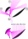 |
Figure 1:
Sketch of the telescope design in the symmetry plane (
 ). This figure shows the carrier
telescope configuration: a gregorian Dragone-Mizuguchi design with the
primary mirror enlarged to 1.5 meter to reduce the main spillover (2a).
The upper panel shows the rays coming from unwanted directions and focused
into the feed: (1a) spillover past the subreflector; (1b) spillover past the
subreflector redirect by the shields; (2a) spillover past the main
reflector; (2b) spillover past the main reflector and redirect by the
shields.
The bottom drawing shows the telescope with rays coming from the direction
of the optical axis and focused in a feed located at the centre of the
focal plane.
The spillover blocked by the shield, (1b) and (2b), is redirected close to the
main beam as shown on the full-antenna pattern in Fig. 2. ). This figure shows the carrier
telescope configuration: a gregorian Dragone-Mizuguchi design with the
primary mirror enlarged to 1.5 meter to reduce the main spillover (2a).
The upper panel shows the rays coming from unwanted directions and focused
into the feed: (1a) spillover past the subreflector; (1b) spillover past the
subreflector redirect by the shields; (2a) spillover past the main
reflector; (2b) spillover past the main reflector and redirect by the
shields.
The bottom drawing shows the telescope with rays coming from the direction
of the optical axis and focused in a feed located at the centre of the
focal plane.
The spillover blocked by the shield, (1b) and (2b), is redirected close to the
main beam as shown on the full-antenna pattern in Fig. 2. |
| Open with DEXTER |
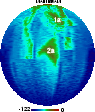 |
Figure 2:
Full antenna pattern, with response normalized to the maximum,
for the carrier configuration. The color table is linear
in dB; the true directivity at the maximum is 49.36 dBi.
Pattern regions related to particular optical structures are identified.
See also the text. |
| Open with DEXTER |
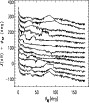 |
Figure 3:
Cuts of full antenna pattern in dB for the carrier configuration.
The lines refer to the antenna response for
between
and
and, from the bottom to the top, with
at steps of
 from
to
(each cut is vertically
shifted for graphic purposes to have the pattern response value at
from
to
(each cut is vertically
shifted for graphic purposes to have the pattern response value at
 equal to the considered value of
).
equal to the considered value of
). |
| Open with DEXTER |
We have conservatively considered the worst case (de Maagt et al. 1998)
for the straylight effect:
we use the antenna pattern
computed at 30 GHz, the channel with the highest spillover and with the
highest Galaxy signal. We also included the shields for the Carrier
Configuration.
The main feature is the spillover (2a) at about  from the
main beam (see also Fig. 2,
where the main beam is located at North pole)
which shows
a response of
from the
main beam (see also Fig. 2,
where the main beam is located at North pole)
which shows
a response of
 dB with respect to the maximum,
i.e.
dB with respect to the maximum,
i.e.
 dBi
(the main beam peak level is at 50 dBi),
extending for few tens of degrees in
and in
(around
dBi
(the main beam peak level is at 50 dBi),
extending for few tens of degrees in
and in
(around
 ,
i.e. always quite close to the direction
of the axis x in the "telescope frame'').
Another relevant
feature is the subreflector spillover (1a), with similar response
level and an angular extension close to the main beam (
,
i.e. always quite close to the direction
of the axis x in the "telescope frame'').
Another relevant
feature is the subreflector spillover (1a), with similar response
level and an angular extension close to the main beam (
 )
as we can see in Fig. 1.
Other features are also located on the northern semisphere, due to the
shields which block rays coming from the southern part of the sphere (see
de Maagt et al. 1998 for a more detailed discussion of their connection
with the optical configuration).
)
as we can see in Fig. 1.
Other features are also located on the northern semisphere, due to the
shields which block rays coming from the southern part of the sphere (see
de Maagt et al. 1998 for a more detailed discussion of their connection
with the optical configuration).
The pattern has been calculated using the
Physical Optics (PO) and its extension, the
Physical Theory of
Diffraction (PTD). Since pattern responses at levels smaller than
about -60 dB, i.e. -10 dBi,
are hard to measure, this is the most accurate method to predict the
side lobe response on the antenna.
The validity of the simulations at very small levels of the far sidelobes
will be tested by measuring the antenna response of a fully
representative copy of the PLANCK
telescope both in compact range and in outdoor far field
test range facilities.
Antenna pattern measurements are needed also for the knowledge
of the near sidelobes (intermediate pattern, see Sect. 3.1).
In fact, mirror distortions and roughness will modify
in particular the intermediate pattern shape
with respect to the shape calculated with the adopted method
that neglects these effects.
Moreover, multiple reflections and diffraction on the focal plane unit
are not taken into account by the PO/PTD analysis and
will modify the intermediate beam shape as well.
The realistic prediction of the intermediate pattern is then
particularly difficult
and the current PO/PTD computation provides only a rough
estimation of the beam shape in these angular regions.
2.3 Simple estimates
Taking the level of Galactic emission and the antenna integrated response
from angular regions at different angles from the beam centre, we can provide
first order estimates of the expected GSC.
The region with
between 1.2
and 2
contains
about 0.5% of the integrated response;
the region between 1.2
and 5
contains about 0.6% of the integrated response
and all the rest of the far pattern (
 )
contains about 1% of the integrated response.
Of course, the remaining main integrated response falls
in the "main'' beam (up to 1.2)
(see also Sect. 3.1 for
a discussion on the choice of these characteristic angles).
In addition, in the main spillover (2a) enters
)
contains about 1% of the integrated response.
Of course, the remaining main integrated response falls
in the "main'' beam (up to 1.2)
(see also Sect. 3.1 for
a discussion on the choice of these characteristic angles).
In addition, in the main spillover (2a) enters 
 %
of the integrated response.
%
of the integrated response.
The sky signal at 30 GHz is known with a pixel size
of about
 by COBE-DMR.
For the present study at 30 GHz the relevant astrophysical source is the
Galaxy emission. While the large-scale Galaxy emission at 30 GHz is quite
well known, for angular scales smaller then a few degrees we can only resort
to extrapolations from existing maps and surveys at lower and higher
frequencies. More precise information will be available
from the next MAP data and, finally, from PLANCK data
themselves.
We have here implemented "small'' angular extrapolations
(see, e.g., Burigana et al. 2000a for further details)
for generating Galaxy maps with resolution of about
by COBE-DMR.
For the present study at 30 GHz the relevant astrophysical source is the
Galaxy emission. While the large-scale Galaxy emission at 30 GHz is quite
well known, for angular scales smaller then a few degrees we can only resort
to extrapolations from existing maps and surveys at lower and higher
frequencies. More precise information will be available
from the next MAP data and, finally, from PLANCK data
themselves.
We have here implemented "small'' angular extrapolations
(see, e.g., Burigana et al. 2000a for further details)
for generating Galaxy maps with resolution of about
 ,
corresponding
to Quad-Cube resolution 7.
,
corresponding
to Quad-Cube resolution 7.
For simple estimates, we note that in the adopted 30 GHz Galaxy map
there are 13
 with a signal (in terms of antenna temperature
  )
larger the 2 mK, 73
with
)
larger the 2 mK, 73
with
 mK and
230
with
mK and
230
with
 mK, while the minimum signal is 0.05 mK
and about the 50% of the sky shows a signal 0.1 mK.
mK, while the minimum signal is 0.05 mK
and about the 50% of the sky shows a signal 0.1 mK.
By combining these numbers with the percentages of integrated responses
falling within the above different angles from the beam centre,
we expect to find
a contamination peaking at about 10 K from the pattern regions
between 1.2
and 5
and at a few
K from the pattern regions
outside 5.
In particular, in the main spillover (2a) we expect a signal peaking at
2 K when it looks at high signal Galactic regions.
Similar contributions are expected from the pattern features
at few tens of degrees from the beam centre.
Of course, smaller contaminations (0.5 K) are expected
when the relevant pattern features look at regions with
low Galactic signal.
K from the pattern regions
between 1.2
and 5
and at a few
K from the pattern regions
outside 5.
In particular, in the main spillover (2a) we expect a signal peaking at
2 K when it looks at high signal Galactic regions.
Similar contributions are expected from the pattern features
at few tens of degrees from the beam centre.
Of course, smaller contaminations (0.5 K) are expected
when the relevant pattern features look at regions with
low Galactic signal.
Numerical calculations, such as those presented
in the next sections, are required for more accurate estimates.
The input map is converted from its original Quad-Cube pixelisation
to a equal area, hierarchic HEALPix pixelisation scheme (Górski et al. 1998),
adopted in the present work
(see also Sect. 3.1 for details
about the nominal resolution of this map).
The final output of the simulation code relevant here are
2 matrices with a number
of rows equal to the considered number of spin-axis positions  for one year of mission (
 here) and
a number of columns equal to the number of considered samplings
along one scan circle (
here) and
a number of columns equal to the number of considered samplings
along one scan circle (
 here).
In the first matrix,
here).
In the first matrix,  ,
we store the pixel numbers corresponding to
the main beam central
directions for the considered
,
we store the pixel numbers corresponding to
the main beam central
directions for the considered
 integrations; they are stored
in HEALPix pixelisation scheme
at
integrations; they are stored
in HEALPix pixelisation scheme
at
 (the number of pixels
 in a full sky map
is related to
in a full sky map
is related to
 by
by
 ,
Górski et al. 1998).
In the second matrix,
,
Górski et al. 1998).
In the second matrix,  ,
we store the antenna temperatures
"observed'' by the considered
portion of the antenna pattern for the above pointing positions.
We neglect here the receiver noise and all the other systematics.
These data streams are the first output of our simulations;
they give immediately
the impact of GSC
and are useful to understand
how this effect changes during the mission.
,
we store the antenna temperatures
"observed'' by the considered
portion of the antenna pattern for the above pointing positions.
We neglect here the receiver noise and all the other systematics.
These data streams are the first output of our simulations;
they give immediately
the impact of GSC
and are useful to understand
how this effect changes during the mission.
From these data streams it is quite simple to obtain
simulated observed maps, that
can be visualized for example in mollweide projection:
we make use of
and
to simply coadd the temperatures
of those pixels observed several times during the mission.
In this way we attribute to each pixel the average of the signals
observed when the antenna pattern, due to the scanning strategy,
is differently oriented in the sky
and thus making Galactic regions with very different signal
intensities enter in the intermediate/far sidelobes;
of course, by coadding different samples of the same location into pixels
the systematic error per pixel is smaller than the systematic error in the
most contaminated sample.
This is because for different samples of the same location on the sky
the sidelobes are pointing towards different regions of the sky, some brighter
and some fainter.
2.5 Power spectra
We can analyse both data streams and maps in terms of power at different
scale-lengths or multipoles (or modes).
In order to analyse separately each scan circle of the simulated data streams
we follow the approach suggested by Puget & Delabrouille (1999) and decompose
the time series from the scan circle in Fourier series:
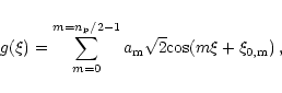 |
(1) |
where  is the signal at the position
identified by an angle
is the signal at the position
identified by an angle  (between 0 and
  )
on the considered scan circle. The
)
on the considered scan circle. The
 coefficients
 and
and
 can be easily computed from the time series
by solving a linear system. The amplitude, ,
of each mode m,
analogous to the multipole
can be easily computed from the time series
by solving a linear system. The amplitude, ,
of each mode m,
analogous to the multipole  of a usual spherical harmonic
expansion, has to be compared with that of the wanted
signal and of other sources of noise.
This approach is particularly interesting for
the data analysis during the mission, as PLANCK will continuously scan
different circles in the sky.
of a usual spherical harmonic
expansion, has to be compared with that of the wanted
signal and of other sources of noise.
This approach is particularly interesting for
the data analysis during the mission, as PLANCK will continuously scan
different circles in the sky.
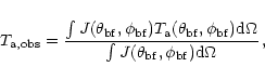
For analysing the maps of coadded signals we use the standard
approach of computing their angular power spectrum.
We produce maps in the HEALPix pixelisation scheme
(Górski et al. 1998) which
takes advantage from the isolatitude of the pixels
for a quick generation of a map
from the coefficients
 of the spherical harmonic expansion
and vice versa (Muciaccia et al. 1997).
[We will show the angular power spectra in terms of
of the spherical harmonic expansion
and vice versa (Muciaccia et al. 1997).
[We will show the angular power spectra in terms of
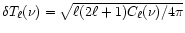 ].
This is a very significant test for evaluating the GSC impact on
PLANCK science, as the estimation of the angular
power spectrum of CMB fluctuations
from the sky maps is one of the main objectives of the PLANCK mission.
It offers also the possibility
of directly comparing the GSC with
astrophysical contaminations
and other sources of instrumental noise.
Of course, it produces a "global'' estimate of GSC effect,
useful in the analysis of the whole sky maps.
].
This is a very significant test for evaluating the GSC impact on
PLANCK science, as the estimation of the angular
power spectrum of CMB fluctuations
from the sky maps is one of the main objectives of the PLANCK mission.
It offers also the possibility
of directly comparing the GSC with
astrophysical contaminations
and other sources of instrumental noise.
Of course, it produces a "global'' estimate of GSC effect,
useful in the analysis of the whole sky maps.
3 Accuracy and tests
The antenna pattern is theoretically known from optical
simulation codes at the desired accuracy and resolution compatible with
the available computing time. The adopted grids have a resolution
much better than those
of currently available sky maps at PLANCK frequencies, although
extrapolations both in frequency and in angular resolution
of existing maps allow us to produce more refined simulated maps
(see, e.g., Burigana et al. 1998, 2000a).
On the other hand, the knowledge of Galactic emission at high resolution
is not particularly relevant here and only small angular extrapolations
up to a resolution of about
 have been implemented.
Given the currently available input map resolution and the adopted
simplified scanning strategies, we are able to derive the power
of GSC only up to
have been implemented.
Given the currently available input map resolution and the adopted
simplified scanning strategies, we are able to derive the power
of GSC only up to
 ,
a mode/multipole range
satisfactory for the study of the smooth features in the
intermediate and far pattern response.
A very good agreement is found with the high resolution computations based
on faster Fourier expansion methods (Wandelt & Górski 2000)
which will be practically necessary for whole sky convolutions
at angular resolutions higher than those adopted in this work.
On the other hand, at larger multipoles, where a more realistic knowledge
of the antenna pattern and the Galaxy emission is necessary for
firm predictions (see Sects. 2.2 and 2.3),
the GSC effects are dominated by other systematics, as discussed in Sect. 5.
,
a mode/multipole range
satisfactory for the study of the smooth features in the
intermediate and far pattern response.
A very good agreement is found with the high resolution computations based
on faster Fourier expansion methods (Wandelt & Górski 2000)
which will be practically necessary for whole sky convolutions
at angular resolutions higher than those adopted in this work.
On the other hand, at larger multipoles, where a more realistic knowledge
of the antenna pattern and the Galaxy emission is necessary for
firm predictions (see Sects. 2.2 and 2.3),
the GSC effects are dominated by other systematics, as discussed in Sect. 5.
3.1 Sky, pattern grids and numerical accuracy
We are interested in producing signal data streams as they would be observed
separately by different angular regions of the antenna pattern
in order to understand the effect of the different
pattern features as they project in the sky during the PLANCK observations.
We have considered here three regions:
 (main pattern);
 (intermediate pattern);
 (far pattern).
We have choosen
(far pattern).
We have choosen
 and
and
 .
Of course, the choice of
.
Of course, the choice of
 and
and
 has to be appropriate to the considered antenna pattern:
for a given telescope design it depends mainly on the considered frequency
and only weakly on the exact feed location on the focal surface.
For the 30 GHz channel, the main beam can be accurately measured in-flight
using planet transits (Mandolesi et al. 1998; Burigana et al. 2000b)
up to response levels of -30 dB (20 dBi)
with respect to the peak response;
has to be appropriate to the considered antenna pattern:
for a given telescope design it depends mainly on the considered frequency
and only weakly on the exact feed location on the focal surface.
For the 30 GHz channel, the main beam can be accurately measured in-flight
using planet transits (Mandolesi et al. 1998; Burigana et al. 2000b)
up to response levels of -30 dB (20 dBi)
with respect to the peak response;
 corresponds to antenna
responses lower than -40 dB (10 dBi),
where the beam response probably becames
highly difficult to measure in-flight;
corresponds to antenna
responses lower than -40 dB (10 dBi),
where the beam response probably becames
highly difficult to measure in-flight;
 roughly divides pattern regions where significant response variations
occur on angular scales less than
from those where
they occur on
degree or much larger scales.
roughly divides pattern regions where significant response variations
occur on angular scales less than
from those where
they occur on
degree or much larger scales.
The observed antenna temperature is given by
 |
(2) |
where J and
are the antenna response and the sky antenna temperature
in the direction given by
.
The convolution of antenna response with the sky and the integration of the antenna
pattern is simply computed by adding the contributions from
all the pixels within the considered solid angle,
at resolutions corresponding to
 respectively for the main, intermediate and far pattern,
in order to take accurately into account the pattern response variations.
The main pattern is given in equispaced cartesian coordinates
with
respectively for the main, intermediate and far pattern,
in order to take accurately into account the pattern response variations.
The main pattern is given in equispaced cartesian coordinates
with
 .
The intermediate pattern and the far pattern
are provided in equispaced "GRASP8'' polar grids
with
.
The intermediate pattern and the far pattern
are provided in equispaced "GRASP8'' polar grids
with
 and
and
 and
and
 ,
respectively.
When we extract all the pixels in the sky that
contribute to the convolution
within the considered solid angle, the exact central position
of each pixel typically does not coincide
with a grid point where the pattern is known.
Simple standard bilinear interpolation (Press et al. 1992)
on the pattern grid has been implemented:
this is fast, robust and accurate enough for the present purposes.
,
respectively.
When we extract all the pixels in the sky that
contribute to the convolution
within the considered solid angle, the exact central position
of each pixel typically does not coincide
with a grid point where the pattern is known.
Simple standard bilinear interpolation (Press et al. 1992)
on the pattern grid has been implemented:
this is fast, robust and accurate enough for the present purposes.
An estimate of the error introduced by
the above discretizations and interpolation/computation methods
can be provided by comparing the convolutions
obtained with different values of
,
for example by increasing
to 1024 for the intermediate pattern convolution. The numerical error
is negligible
(
 1 K,
1 K,
 0.5 K
or
0.2 K for the convolutions with the main,
intermediate and far pattern, respectively).
Thus, the real uncertainty of the currently available
straylight analyses is dominated by the uncertainty of our knowledge
of the antenna pattern (particularly for
the intermediate pattern, see Sect. 2.2) and of the Galaxy emission.
0.5 K
or
0.2 K for the convolutions with the main,
intermediate and far pattern, respectively).
Thus, the real uncertainty of the currently available
straylight analyses is dominated by the uncertainty of our knowledge
of the antenna pattern (particularly for
the intermediate pattern, see Sect. 2.2) and of the Galaxy emission.
3.2 Tests with schematic skies and patterns
Checking the consistency of the part of the code that
computes the signal entering in the main beam and in the intermediate
pattern is quite direct: we simply expect that the maps extracted from
the corresponding data streams are respectively very similar or
roughly proportional
(according to the fractional signal entering at
 )
to Galactic emission pattern, except for the beam smoothing.
)
to Galactic emission pattern, except for the beam smoothing.
Testing the validity of the computation of the signal entering
the far pattern is not immediate, because it does not reflect
in a simple way the Galactic emission pattern.
We have verified the consistency of our simulation code
by exploring simple cases for which we can
easily predict the large-scale symmetries of the maps derived from
the data streams observed by the far pattern.
We have assumed a simple antenna pattern, centred on the optical axis
and perfectly symmetric
in
,
given by the sum of two Gaussian shapes, one for the
main beam and one for the main spillover located at
 from
the main beam centre, plus a constant low response level.
We have performed tests with the following different
very simple input skies:
i) a spot at North Galactic pole:
it produces a map with a well defined slab on the Galactic plane;
ii) a slab on the ecliptic plane: the corresponding map shows a
signal maximum at the ecliptic poles and decreasing toward the ecliptic plane;
iii) a slab on the Galactic plane: the corresponding map
shows a signal maximum at the Galactic poles and decreasing toward the Galactic
plane, where it exhibits small longitudinal modulations related
to those of the solid angle subtended by the main spillover
(this is due to the scanning symmetry with respect to ecliptic coordinates
and not with respect to Galactic ones).
We have also verified that the angular power spectrum of the these maps
presents a main peak at the multipole
from
the main beam centre, plus a constant low response level.
We have performed tests with the following different
very simple input skies:
i) a spot at North Galactic pole:
it produces a map with a well defined slab on the Galactic plane;
ii) a slab on the ecliptic plane: the corresponding map shows a
signal maximum at the ecliptic poles and decreasing toward the ecliptic plane;
iii) a slab on the Galactic plane: the corresponding map
shows a signal maximum at the Galactic poles and decreasing toward the Galactic
plane, where it exhibits small longitudinal modulations related
to those of the solid angle subtended by the main spillover
(this is due to the scanning symmetry with respect to ecliptic coordinates
and not with respect to Galactic ones).
We have also verified that the angular power spectrum of the these maps
presents a main peak at the multipole  and secondary peaks
at its harmonic frequencies, as expected
from the
symmetry of the adopted far pattern.
and secondary peaks
at its harmonic frequencies, as expected
from the
symmetry of the adopted far pattern.
4 Simulations results
We have considered two options for the PLANCK Carrier configuration.
The first is exactly that considered by de Maagt et al. (1998)
with
 and including shields. In the second case
we have used the same optical
results but with
and including shields. In the second case
we have used the same optical
results but with
 :
the
corresponding results are then only
indicative, being not perfectly consistent because the spacecraft design
would be slightly different for this
configuration; on the other hand,
this case is instructive because it allows us to start addressing
the question of the dependence of
GSC on a basic parameter of the scanning strategy.
We have considered the antenna pattern at 30 GHz
with the beam centre located at
:
the
corresponding results are then only
indicative, being not perfectly consistent because the spacecraft design
would be slightly different for this
configuration; on the other hand,
this case is instructive because it allows us to start addressing
the question of the dependence of
GSC on a basic parameter of the scanning strategy.
We have considered the antenna pattern at 30 GHz
with the beam centre located at
 and
and
 .
.
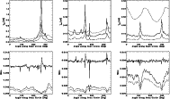 |
Figure 4:
Top panels: absolute signals entering the main (solid lines),
intermediate (multiplied by 50 for graphic purposes, dotted-dashed lines)
and far (multiplied by 100, dashed lines) pattern
for the case
for three scan circles corresponding
to spin axis longitudes of 0,
120
and 270
from left to right.
The angle along the scan circle, ranging between 0
and 360,
is set to 0 at the beginning of the stream from each scan circle.
Bottom panels: the ratios between the signals shown in the top panels,
intermediate/main (solid lines),
far/main (multiplied by 0.1, dotted-dashed line) and far/intermediate
(multiplied by
 ,
dashed lines). ,
dashed lines). |
| Open with DEXTER |
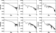 |
Figure 6:
Fourier decomposition, see Eq. (1),
of the signal at
 from
the scan circles of Fig. 4 (
,
top panels)
and 5 (
,
bottom panels).
From the left to right: spin axis longitudes of 0,
120
and 270.
Dashed and solid horizontal lines represent the white noise
for one and four receivers, respectively.
from
the scan circles of Fig. 4 (
,
top panels)
and 5 (
,
bottom panels).
From the left to right: spin axis longitudes of 0,
120
and 270.
Dashed and solid horizontal lines represent the white noise
for one and four receivers, respectively. |
| Open with DEXTER |
Figures 4 and 5 show the absolute signals
entering the main, intermediate and far pattern
and their ratios for the data streams of three representative scan circles
for
and
,
respectively.
Note that the signal entering the intermediate pattern is
roughly proportional to that in the main beam:
two main relative maxima typically appear, related to the two crossings
of the Galactic plane.
The signal from the far sidelobes exhibits a clearly
different and shifted angular behaviour, although
two main relative maxima are again typically
present. These are mainly due to the contributions
from the pattern features (1a)
in the cases of the left and central panels,
and to the main spillover (2a) in the case of the right panels,
as they cross the Galactic plane. Note in fact the displacement
between the maximum signal from the main and far pattern,
of few tens of degrees (several tens of degrees)
for the left and central panel (right panel).
We have applied the Fourier series decomposition
(see Fig. 6) described by Eq. (1)
to the sum of intermediate and far pattern (i.e. for
)
data streams from the scan circles shown in Figs. 4 and 5.
The same decomposition has been applied to white noise data streams, computed according
to the LFI sensitivity at 30 GHz (see, e.g., Maino et al. 1999)
averaged over a number of scan circles that spans an ecliptic longitude length
arc equal to the
FWHM = 33', i.e. essentially the sensitivity
corresponding to a half-year mission.
The white noise power is above that of the signal entering at
,
for practically all the modes
 ,
becaming 10 times larger
at
,
becaming 10 times larger
at
 ;
this is essentially due to the strong decreasing
of Galaxy fluctuations at small angular scales.
;
this is essentially due to the strong decreasing
of Galaxy fluctuations at small angular scales.
No significant differences are found by varying
from
 to
;
for this reason and for the sake of simplicity,
we will show in what follows only the results for
to
;
for this reason and for the sake of simplicity,
we will show in what follows only the results for
 ,
the angle for which the optical simulations have been
appropriately performed.
,
the angle for which the optical simulations have been
appropriately performed.
All simulated data streams for a 1 yr mission
are shown in Fig. 7
for the case
(similar patterns are obtained in the case
). In the right panel, note the vertical high signal line
at
 ,
corresponding to the main spillover (2a),
and the two high signal features, close to this line, at
about
,
corresponding to the main spillover (2a),
and the two high signal features, close to this line, at
about
 and
and
 ,
corresponding to
the pattern features at few tens of degrees from the beam centre.
Note also how the azimuthally asymmetric
far pattern reflects in the
large difference between the two halfs (along
,
corresponding to
the pattern features at few tens of degrees from the beam centre.
Note also how the azimuthally asymmetric
far pattern reflects in the
large difference between the two halfs (along  axis) of the right panel
of Fig. 7 corresponding to the first and second six months
of observation.
This redundancy can be exploited for an efficient subtraction of GSC
in the data analysis.
axis) of the right panel
of Fig. 7 corresponding to the first and second six months
of observation.
This redundancy can be exploited for an efficient subtraction of GSC
in the data analysis.
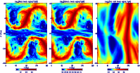 |
Figure 7:
Synthetic view of the data stream from all scan
circles for
.
The ecliptic coordinates
and  refer here to the longitude and latitude of the telescope axis.
[For graphic purposes, in this plot the range
of
between refer here to the longitude and latitude of the telescope axis.
[For graphic purposes, in this plot the range
of
between
 and
and
 refer to the second half of each scan circle]. Compare with Fig. 4.
 |
| Open with DEXTER |
By coadding the data streams as described in Sect. 2.5
we can obtain the corresponding maps.
This is shown in Fig. 8 for the case
,
by coadding the simulated data from the whole year.
![\begin{figure}
\par\includegraphics[width=8.8cm,height=9.7cm,clip]{buriganac_10314_fig8.ps}\end{figure}](/articles/aa/full/2001/25/aa10314/Timg126.gif) |
Figure 8:
Maps of GSC in Galactic coordinates from the coadding of the simulated data
of the whole year for the case
.
[For graphic purposes, the pixels close to the ecliptic poles,
not observed because of the adopted
scanning strategy parameters, have been filled with values close to those
of the adjacent pixels]. In the bottom panel,
note the two arcs corresponding to the main spillover (2a) and the central contaminations
corresponding to the pattern features at a few tens of degrees from the beam centre.
They clearly correspond to the features in the right panel of Fig. 7.
Note also the wide "stripe'' connecting the two ecliptic poles, which corresponds
to the sky region observed a single time in the current 1 yr simulation, owing to
the considered effective scanning strategy. [The color at the left (right) edge
of the color bar refers to the minimum (maximum) temperature
reported in each panel]. |
| Open with DEXTER |
As apparent in Fig. 8,
the map from the intermediate pattern is roughly proportional to that derived
from the main pattern; the relative intensities are roughly scaled by the
fraction of integrated response entering the two portions of the antenna pattern.
On the contrary, the sky "observed'' by the far pattern is very different.
The signal is higher close to the Galactic plane, because of the features
in the antenna pattern within
 from the main beam, and
at about
from the Galactic plane, because of the signal entering the main spillover (2a).
from the main beam, and
at about
from the Galactic plane, because of the signal entering the main spillover (2a).
We have computed the angular power spectra of these GSC maps
(see Fig. 9)
and compared them with the theoretical angular power spectrum
of the white noise for a single 30 GHz receiver
and for four receivers
and with a typical CMB anisotropy
angular power spectrum (a tilted -
 - power spectrum with standard
CDM cosmological parameters and approximately COBE normalized)
and with that of Galaxy fluctuations as seen by
the main pattern.
The most important contamination in terms of angular power spectrum derives
from the signal entering in the intermediate pattern when all the sky is considered;
on the contrary, if we consider only the regions at
- power spectrum with standard
CDM cosmological parameters and approximately COBE normalized)
and with that of Galaxy fluctuations as seen by
the main pattern.
The most important contamination in terms of angular power spectrum derives
from the signal entering in the intermediate pattern when all the sky is considered;
on the contrary, if we consider only the regions at
 ,
more crucial for PLANCK main science,
the largest contributions to the GSC power spectrum
derive from the far sidelobes.
In general, the GSC power spectrum is larger than the white noise one
at low multipoles (
,
more crucial for PLANCK main science,
the largest contributions to the GSC power spectrum
derive from the far sidelobes.
In general, the GSC power spectrum is larger than the white noise one
at low multipoles (
 )
but their ratio becames less than 1/10
at
)
but their ratio becames less than 1/10
at
 and decreases further at larger multipoles,
due to their different dependence on .
and decreases further at larger multipoles,
due to their different dependence on .
![\begin{figure}
\par\includegraphics[width=8.4cm,height=9.8cm,clip]{buriganac_10314_fig9.ps}\end{figure}](/articles/aa/full/2001/25/aa10314/Timg133.gif) |
Figure 9:
Comparison between the angular power spectrum of GSC from different
pattern regions and that of the CMB anisotropy (thick solid line)
and of the receiver white noise (dotted lines; upper line: a single receiver;
lower line: four receivers).
Galaxy fluctuation power spectrum as seen by the main pattern
without map cuts (upper dotted-dashed line) and
by considering only the regions
at
(lower dotted-dashed line).
Angular power spectra of GSC from the
intermediate pattern without Galactic cut
(upper solid - green - line) and
at
(lower dashed - green - line)
and from the
far pattern without Galactic cut
(lower solid - red - line) and
at
(upper dashed - red - line).
See also the text. |
| Open with DEXTER |
5 Comparison with other sources of noise
Many other sources of contamination,
both instrumental and astrophysical in origin,
may affect PLANCK observations.
We approach here a first comparison among the effects introduced by some of
these systematics.
5.1 Other kinds of instrumental noise
The impact of main beam distortions introduced by optical aberrations
on PLANCK measurements has been carefully
studied in several works
(see, e.g., Burigana et al. 1998, 2000a; Mandolesi et al. 1997, 2000a).
Burigana et al. (1998) discussed the impact of the main beam distortions
for the representative case of an elliptical main beam shape.
In general, the absolute rms additional noise, in the range of few K,
increases with the beam ellipticity.
The combined effect of main beam distortions
and of Galaxy emission fluctuations
increases the additional error at 30 GHz by a factor 3
with respect to the case of the essentially pure CMB fluctuation sky
at high Galactic latitudes, whereas it produces only a small additional
effect at higher LFI frequencies. In addition, the combined effect
of main beam distortions and extragalactic source fluctuations is found
to be very small at all LFI frequencies
(Burigana et al. 2000a) compared
to the noise induced by beam distortions in the case of a pure CMB sky.
Then, we focus further on the impact of the main beam distortions
on the determination of angular power spectrum of CMB fluctuations
by considering the idealized case of the above pure CMB sky fluctuations.
The kind and the magnitude of optical distortions
depend on the details of the optical design;
for aplanatic configurations currently under study (see, e.g., Villa et al. 1998;
Mandolesi et al. 2000b) the typical main beam shape is roughly elliptical
owing to the strong reduction of the coma distortion.
We computed a full year
simplified simulation
both for a pure symmetric Gaussian beam
with
 and for an elliptical Gaussian beam with axial
ratio r = 1.3 and with the same effective resolution (
and for an elliptical Gaussian beam with axial
ratio r = 1.3 and with the same effective resolution (
 )
of
the symmetric beam (r=1). We
shift the spin axis at steps of 5' and consider a step of 5' between
two samplings on the same scan circle.
We computed the difference between the maps obtained from the elliptical and
the symmetric
beam by coadding the corresponding data streams and calculate the angular
power spectrum of this difference map
in order to understand which range of multipoles is
mainly affected.
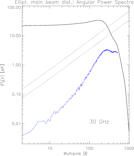
As expected (see Fig. 10), this effect is particularly relevant
at quite large multipoles,
close to the CMB peak, where GSC power significantly decreases:
the magnitude, of course, is related to the value of r.
)
of
the symmetric beam (r=1). We
shift the spin axis at steps of 5' and consider a step of 5' between
two samplings on the same scan circle.
We computed the difference between the maps obtained from the elliptical and
the symmetric
beam by coadding the corresponding data streams and calculate the angular
power spectrum of this difference map
in order to understand which range of multipoles is
mainly affected.
As expected (see Fig. 10), this effect is particularly relevant
at quite large multipoles,
close to the CMB peak, where GSC power significantly decreases:
the magnitude, of course, is related to the value of r.
From optical simulations we know that r typically increases with the distance
from the beam centre. From the present simulations we infer that a value
of r smaller than 1.3, say less than 1.1 (1.2)
when the response level normalized to the maximum
is less than -3 dB (-20 dB),
is good enough to avoid significant contamination in the data,
in agreement with the indications inferred
on the basis of the approximations of Burigana et al. (1998)
for the rms noise added by a main beam elliptical distortion.
 |
Figure 10:
Angular power spectrum introduced by an elliptical main beam distortion
with r=1.3 (lower - blue - line). See also the text. |
| Open with DEXTER |
The 1/f noise due to amplifier noise temperature fluctuations
induced by gain fluctuations in the PLANCK LFI receiver and its dependence
on the relevant instrumental parameters has been studied
by Seiffert et al. (1997). It introduces additional noise in
PLANCK observations which appears as stripes in final maps
(Janssen et al. 1996)
owing to the particular PLANCK scanning strategy.
We have recently carried out detailed studies
(Maino et al. 1999 and reference therein) on its effect on PLANCK LFI
measurements and on the efficiency of destriping algorithms
based on the use of the crossings between different scan circles
(Bersanelli et al. 1996; Delabrouille 1998)
for a wide set of PLANCK scanning strategies.
We extend here their simulations by relaxing the hypothesis of a symmetric beam
to study the impact of main beam distortion on the destriping algorithm.
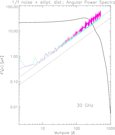
In Fig. 11 we show the angular power spectrum of the receiver noise
before and after applying the destriping algorithm when we
include also the above elliptical distortion,
for a simple scanning strategy with
and a beam location
at
 ,
,
 ,
a "mean''
choice regarding the destriping efficiency (Maino et al. 1999).
We find that the destriping efficiency is not
significantly affected by the additional uncertainty
introduced by the "systematic'' differences among
the observed temperatures resulting from different orientations of the main beam
at the crossing points of different scan circles.
,
a "mean''
choice regarding the destriping efficiency (Maino et al. 1999).
We find that the destriping efficiency is not
significantly affected by the additional uncertainty
introduced by the "systematic'' differences among
the observed temperatures resulting from different orientations of the main beam
at the crossing points of different scan circles.
 |
Figure 11:
Angular power spectrum of the 1/f noise before
(upper - red - line with blobs)
and after (lower - green - line, close to the level of the theoretical white noise
power spectrum for a single receiver) the destriping
for the case of an elliptical main beam. |
| Open with DEXTER |
As is evident by comparing Figs. 9-11, there is a crucial difference between
the angular power spectra of GSC, main beam distortion induced noise and 1/f noise.
The GSC affects particularly the determination of the CMB angular
power spectrum at low multipoles, whereas main beam distortions
are critical at large multipoles. The 1/f noise affects both high
and low multipoles, but destriping algorithms are particularly
efficient at removing high multipole features in the power spectrum.
It is clear that all these effects have to be reduced both via
hardware and software. The 1/f noise can be reduced independently
of the other two, its magnitude being related essentially to the
instrument stability and to the scanning strategy (Maino et al. 1999).
On the other hand, a compromise has to be reached between GSC
and main beam distortion noise, both being related mainly to the
optical design. As discussed in Mandolesi et al. (2000a), for
a given telescope design, their
relative weight is controlled by the edgetaper.
The optical design has to be optimized to find a trade-off
to reduce the combined impact of these two effects.
5.2 Astrophysical contamination
The impact of foreground on the primary cosmological goal of the
PLANCK mission
has been extensively studied in the literature for
the areas concerning both Galactic and extragalactic contaminations,
of discrete and diffuse origin;
PLANCK itself will be a good opportunity for studying cluster
physics, many classes
of extragalactic and Galactic sources and the diffuse emission
from the Galaxy (see, e.g., De Zotti 1999a and references therein).
Many approaches have been studied to separate
the different components of the microwave sky and for deriving
their angular power spectra (see, e.g., Tegmark & Esftathiou 1996; Hobson et al. 1998;
Baccigalupi et al. 2000b, and references therein).
We consider here the foreground
impact on CMB science and their comparison with the effect of instrumental
systematics.
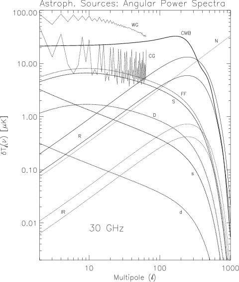
In Fig. 12 we report several estimates of the angular power
spectra of different astrophysical components.
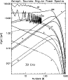 |
Figure 12:
Angular power spectrum of different sources of astrophysical contamination
compared with the CMB angular power spectrum (thick solid line, labelled with "CMB'')
and that of the white noise power spectrum for four receivers
(dotted line, "N'').
See the text for the meaning of the other lines and labels. |
| Open with DEXTER |
Though depending on the considered region, the Galaxy angular power spectrum,
expressed in terms of
 ,
is known to decrease with multipole order :
we show here the power spectrum derived from the map observed by
the adopted main pattern by cutting
(lower thin dotted-dashed line, "CG'') or not (upper thin dotted-dashed line, "WG'')
the region
at
,
is known to decrease with multipole order :
we show here the power spectrum derived from the map observed by
the adopted main pattern by cutting
(lower thin dotted-dashed line, "CG'') or not (upper thin dotted-dashed line, "WG'')
the region
at
 and the power spectra proposed by
Tegmark & Esftathiou (1996) for free-free (thick dotted line, "FF''),
synchrotron (upper thick dotted-dashed line, "S'') and dust (upper thick dashed line, "D'') emission
at relevant Galactic latitudes.
We also show for comparison the power spectra for synchrotron
(lower thick dotted-dashed line, "s'') and dust (lower thick dashed line, "d'') as derived
by Prunet et al. (1998) and Bouchet et al.(1999) for
a sky patch at medium latitudes.
Of course, Galaxy contamination strongly depends on the considered region.
and the power spectra proposed by
Tegmark & Esftathiou (1996) for free-free (thick dotted line, "FF''),
synchrotron (upper thick dotted-dashed line, "S'') and dust (upper thick dashed line, "D'') emission
at relevant Galactic latitudes.
We also show for comparison the power spectra for synchrotron
(lower thick dotted-dashed line, "s'') and dust (lower thick dashed line, "d'') as derived
by Prunet et al. (1998) and Bouchet et al.(1999) for
a sky patch at medium latitudes.
Of course, Galaxy contamination strongly depends on the considered region.
In terms of
,
Poisson fluctuations from extragalactic
unresolved discrete sources increase approximately proportionally to
the multipole .
We show here, separately for radiosource (thin solid lines, "R'') and
the far infrared galaxy (thin dashed lines, "IR''),
the Poisson fluctuation power spectra predicted by Toffolatti et al. (1998)
as recently revised by Toffolatti et al. (1999),
De Zotti et al. (1999b) and references therein,
on the basis of current source counts and assuming evolution
models and spectra in agreement with current data,
when sources above 1 Jy (upper curves)
or 100 mJy (lower curves) are detected and subtracted. Of course
radiosources dominate at low frequencies.
We have taken into account here a Gaussian (FWHM=33') beam smoothing
in all cosmological and astrophysical angular
power spectra and consequently neglected it in the receiver noise
angular power spectrum.
At low multipoles, Galaxy contamination is larger then instrumental effects,
dominated by the GSC (and possible residual 1/f noise);
on the other hand, if the Galaxy emission and anisotropy can be modelled
at a few percent accuracy and at high Galactic latitudes, instrumental
effects can became comparable with the residual Galaxy contamination.
If not appropriately taken into account in the data analysis, main beam distortions
may introduce at high multipoles an additional contamination
comparable with that introduced from radiosource fluctuations, after their
subtraction at few hundreds mJy level.
6 Conclusions
We have studied the impact of GSC on PLANCK observations at 30 GHz,
by considering different and complementary evaluation approaches:
absolute and relative quantification of the impact on scan circle
data streams, Fourier decomposition of scan circle signals,
computation of maps of GSC and evaluation of their angular power
spectra. These different methods allow us to focus on different
aspects of GSC.
No relevant differences are found by varying the angle
between the spin axis and the telescope line of sight
from
to
.
Our simulations show that
the GSC peaks at values of about  K (a value comparable with the sensitivity per pixel),
mainly due to the signal entering at few degrees from the beam centre.
Such values are found in the regions quite close to the Galactic plane,
where in any case the "direct'' (i.e. observed by the main beam)
contamination from the Galaxy prevents an accurate knowledge
of CMB fluctuations, as it is next to impossible to remove
the Galactic signals to accuracy better than few %.
These large contamination values, although
critical for CMB anisotropy measurements near the Galactic plane,
are not crucial for the
determination of Galaxy emission, which is several orders of magnitude
larger.
K (a value comparable with the sensitivity per pixel),
mainly due to the signal entering at few degrees from the beam centre.
Such values are found in the regions quite close to the Galactic plane,
where in any case the "direct'' (i.e. observed by the main beam)
contamination from the Galaxy prevents an accurate knowledge
of CMB fluctuations, as it is next to impossible to remove
the Galactic signals to accuracy better than few %.
These large contamination values, although
critical for CMB anisotropy measurements near the Galactic plane,
are not crucial for the
determination of Galaxy emission, which is several orders of magnitude
larger.
By considering all the pixels in the sky, the typical values of GSC
are less than 50% of the white noise sensitivity per pixel.
The most crucial contamination
derives from the signal entering in the far pattern, in spite of its
peak values, of about 4 K, smaller than those obtained for the
intermediate pattern regions.
In fact, although this effect does not seem to be very large in amplitude
(indeed, being nominally subdominant to the power spectrum of
the expected receiver noise)
it does dominate the GSC at medium and high Galactic latitudes,
which are critical regions for the extraction of the best quality results
on CMB anisotropy.
This also could be critical for
the PLANCK polarization measurements which will take advantage
of the two patches close to the ecliptic poles
where the sensitivity will be several times better than the average,
according to the scanning strategy and the feed array
arrangement.
As expected on the basis of the behaviour of Galaxy emission angular power spectrum,
the GSC affects the determination of the CMB angular power spectrum
mainly in the low multipole region and much less at large multipoles,
particularly when compared with the other instrumental effects considered here,
the main beam distortion and the 1/f noise.
The additional noise introduced by the main beam distortion
can be in principle subtracted in the data analysis, provided that the beam pattern
is accurately reconstructed.
Of course, a substantial improvement in the data analysis is necessary
to jointly treat all the systematics, of instrumental and astrophysical origin.
From the telescope design point of view, the best optimization of the edge taper
requires a trade-off between the main beam distortion
and the GSC effects.
Color figures can be obtained from the electronic form
of this paper or via e-mail request to burigana@tesre.bo.cnr.it.
Acknowledgements
We acknowledge stimulating and helpful discussion with
J. Delabrouille and J. L. Puget; we gratefully thank
P. de Maagt and J. Tauber for having promptly provided us
with their optical simulation results.
We wish to thank the referee for constructive comments.
- Baccigalupi, C., Burigana, C., Perrotta, F., et al. 2000a, A&A, in press [astro-ph/0009135]
In the text
- Baccigalupi, C., Bedini, L., Burigana, C., et al. 2000b, MNRAS, 318, 769
In the text
NASA ADS
- Balbi, A., Ade, P., Bock, J., et al. 2000, ApJ, 545, L1
In the text
NASA ADS
- Bennett, C. L., Banday, A. J., Gòrski, K. M., et al. 1996a, ApJ, 464, L1
In the text
NASA ADS
- Bennett, C. L., et al. 1996b, Amer. Astron. Soc. Meet., 88.05
In the text
- Bersanelli, M., et al. 1996, ESA, COBRAS/SAMBA Report on the Phase A
Study, D/SCI(96)3
In the text
- Bouchet, F. R., Prunet, S., & Sethi, S. K. 1999, MNRAS, 302, 663
NASA ADS
- Burigana, C., Malaspina, M., Mandolesi, N., et al. 1997, Int. Rep. TeSRE/CNR 198/1997, November [astro-ph/9906360]
In the text
- Burigana, C., Maino, D., Mandolesi, N., et al. 1998, A&AS, 130, 551
In the text
NASA ADS
- Burigana, C., Maino, D., Mandolesi, N., et al. 2000a, Astroph. Lett. Comm., 37, 253
In the text
- Burigana, C., Natoli, P., Vittorio, N., Mandolesi, N., & Bersanelli, M. 2000b [astro-ph/0012273]
In the text
- De Bernardis, P., Ade, P. A. R., Bock, J. J., et al. 2000, Nature, 404, 955
In the text
NASA ADS
- Delabrouille, J. 1998, A&AS, 127, 555
In the text
NASA ADS
- De Maagt, P., Polegre, A. M., & Crone, G. 1998, PLANCK - Straylight Evaluation of the Carrier Configuration, Technical Report ESA, PT-TN-05967, 1/0
In the text
- De Zotti, G., Toffolatti, L., Argüeso Gómez, F., et al. 1999a,
Proceedings of the EC-TMR Conference
3 K Cosmology, Roma, Italy, 5-10 October 1998,
AIP Conference Proc. 476, ed. Maiani L., Melchiorri F., & Vittorio N.,
204 [astro-ph/9902103]
In the text
- De Zotti, G., Gruppioni, C., Ciliegi, P., Burigana, C., & Danese, L.
1999b, New Astron., 4, 481
In the text
NASA ADS
- Górski, K. M., Banday, A. J., Bennett, C. L., et al. 1996, ApJ, 464, L11
In the text
NASA ADS
- Górski, K. M., Hivon, E., & Wandelt, B. D. 1998,
Proceedings of the MPA/ESO Conference on
Evolution of Large-Scale Structure: from Recombination to
Garching, ed. A. J. Banday, R. K. Sheth, & L. Da Costa, 37
[astro-ph/9812350]
In the text
- Hanany, S., Ade, P., Balbi, A., et al. 2000, ApJ, 545, L5
In the text
NASA ADS
- Hobson, M. P., Jones, A. W., Lasenby, A. N., & Bouchet, F. R. 1998, MNRAS, 300, 1
In the text
NASA ADS
- Jaffe, A. H., Ade, P. A. R., Balbi, A., et al. 2000, Phys. Rev. Lett., submitted [astro-ph/0007333]
In the text
- Janssen, M., Scott, D., White, M., et al. 1996 [astro-ph/9602009]
In the text
- Lange, A. E., Ade, P. A. R., Bock, J. J., et al. 2000, Phys. Rev. D, submitted [astro-ph/0005004]
In the text
- Maino, D., Burigana, C., Maltoni, M., et al. 1999, A&AS, 140, 383
In the text
NASA ADS
- Mandolesi, N., Bersanelli, M., Burigana, C., et al. 1997, Int. Rep. TeSRE/CNR 199/1997, November
In the text
- Mandolesi, N., et al. 1998, PLANCK LFI, A Proposal Submitted to the
ESA
In the text
- Mandolesi, N., Bersanelli, M., Burigana, C., et al. 2000a, A&AS, 145, 323
In the text
NASA ADS
- Mandolesi, N., Bersanelli, M., Burigana, C., & Villa, F. 2000b, Astroph. Lett. Comm., 37, 151
In the text
- Muciaccia, P. F., Natoli, P., & Vittorio, N. 1997, ApJ, 488, L63
In the text
NASA ADS
- Prunet, S., Sethi, S. K., Bouchet, F. R., & Miville-Deschenes, M. A. 1998, A&A, 339, 187
In the text
NASA ADS
- Press, W. H., Teukolsky, S. A., Vetterling, W. T., & Flannery, B. P. 1992,
Numerical Recipes in Fortran, second edition (Cambridge University Press)
In the text
- Puget, J. L., et al. 1998, HFI for the PLANCK Mission, A Proposal
Submitted to the ESA
In the text
- Puget, J. L., & Delabrouille, J. 1999,
HFI Sidelobe Straylight Requirement Document - 2nd Revision - March 16, 1999
In the text
- Seiffert, M., Burigana, C., Mandolesi, N., et al. 1997, Rev. Scient. Instrum., submitted
In the text
- Smoot, G. F., Bennett, C. L., Kogut, A., et al. 1992, ApJ, 396, L1
In the text
NASA ADS
- Tegmark, M., & Efstathiou, G. 1996, MNRAS, 281, 1297
In the text
NASA ADS
- Toffolatti, L., Argüeso Gómez, F., De Zotti, G., et al. 1998, MNRAS, 297, 117
In the text
NASA ADS
- Toffolatti, L., De Zotti, G., Argüeso Gómez, F., & Burigana, C. 1999, in Proc. Intern. Conf.: Microwave Foregrounds, ed. A. de Oliveira-Costa, & M. Tegmark, Conf. Ser., 181, 153 [astro-ph/9902343]
In the text
- Villa, F., Mandolesi, N., & Burigana, C. 1998, Int. Rep. TeSRE/CNR 221/1998, September
In the text
- Wandelt, B. D., & Górski, K. M. 2000, Phys. Rev. D, submitted
[astro-ph/0008227], see also TAC report Planck Straylight Modelling,
In the text
http://www.tac.dk/wandelt/papers.html
Copyright ESO 2001
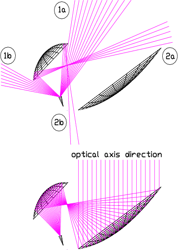

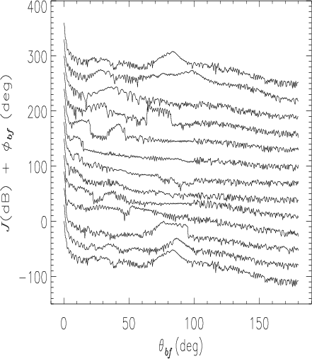
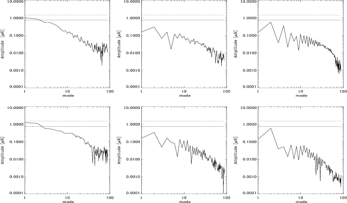
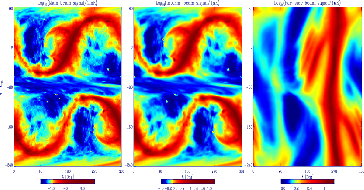
![\begin{figure}
\par\includegraphics[width=8.8cm,height=9.7cm,clip]{buriganac_10314_fig8.ps}\end{figure}](/articles/aa/full/2001/25/aa10314/img126.gif)
![\begin{figure}
\par\includegraphics[width=8.4cm,height=9.8cm,clip]{buriganac_10314_fig9.ps}\end{figure}](/articles/aa/full/2001/25/aa10314/img133.gif)