A&A 369, 1122-1139 (2001)
DOI: 10.1051/0004-6361:20010171
I. Arregui - R. Oliver - J. L. Ballester
Departament de Física, Universitat de les Illes Balears, 07071 Palma de Mallorca, Spain
Received 4 August 2000 / Accepted 26 January 2001
Abstract
High resolution observations of the solar corona made with instruments
onboard the SOHO and TRACE spacecrafts have provided new evidence
for the presence of oscillations in a variety of coronal magnetic
structures. Most of these observations have been interpreted in
terms of linear standing or propagating magnetohydrodynamic (MHD) waves,
but the theoretical understanding is far from complete since
analytical solutions to the linearised MHD wave equations can only be
found for very simple magnetic configurations. Taking into account that
the solar corona is basically structured by force-free magnetic fields, our
purpose in this paper is to present the derivation of the linear MHD
wave equations for a two-dimensional force-free magnetic field
configuration having longitudinal invariance, as well as to
introduce a numerical code to solve the resulting system of coupled
partial differential equations. The accuracy of the code has been
checked by numerically solving two cases for which analytical or
simple numerical solutions exist. To our knowledge, this is the only
two-dimensional code developed to study the normal MHD modes of oscillation of
a general force-free field with longitudinal invariance.
Key words: magnetohydrodynamics - methods: numerical - Sun: oscillations - Sun: magnetic fields
Multiwavelength observations of the solar corona, obtained by both ground-based telescopes and instruments onboard spacecrafts, have revealed the high complexity of its structuring by magnetic fields. These observations show a variety of coronal structures such as loops and arcades, where the magnetic field is closed, or plumes and coronal holes, where the magnetic field is open.
Coronal seismology is becoming an important field of research within solar coronal physics and firm evidence about the existence of oscillations in different coronal structures has been provided by instruments onboard SOHO and TRACE spacecrafts. For instance, DeForest & Gurman (1998) have reported observations, made with EUV on board SOHO, of quasi-periodic perturbations in the brightness of FeIX and FeX emission lines in coronal plumes. The perturbations propagate outward at 75-150 km s-1 with periods of 10-15 min. These compressive perturbations were interpreted as slow magnetoacoustic waves by Ofman et al. (1999, 2000a). EUV brightenings in active region coronal loops have been observed with TRACE by Nightingale et al. (1999), who have also interpreted them as compressional waves. Robbrecht et al. (1999) using simultaneously EIT, onboard SOHO, and TRACE, have pointed out the existence of weak perturbations in loops, originating at the footpoints, propagating along them with an apparent speed of 130 km s-1. They suggest that these disturbances are slow magnetoacoustic waves propagating in coronal loops. Aschwanden et al. (1999), using TRACE, detected spatial oscillations of coronal loops with a transverse amplitude of about 4000 km and a mean period of 280 s. They suggest that the oscillation appears to be a standing wave with fixed nodes at the footpoints and that a fast kink mode seems to provide the best agreement with observations. Moreover, the damping of the oscillation has been explained by dissipation through viscous or resistive processes (Nakariakov et al. 1999; Roberts 2000) or by means of a mechanism based on the topology of magnetic field lines (Schrijver & Brown 2000). De Moortel et al. (2000) have also reported TRACE observations of coronal loop oscillations having periods of 180-420 s and outward propagating velocities of 70-165 kms-1. They have explained these observations in terms of slow magnetoacoustic waves propagating along the loops. Ofman et al. (1997, 2000b), using UVCS onboard SOHO, have detected quasi-periodic variations in the polarised brightness in polar coronal holes. Again, these observations have been explained in terms of density fluctuations caused by compressional waves propagating in polar coronal holes.
Most of the above observations, and many others reported in previous works,
can be interpreted in terms of linear MHD
waves and, from this point of view, investigations of adiabatic standing MHD
waves in coronal magnetic configurations, such as coronal magnetic arcades,
have been undertaken (e.g. Oliver et al. 1993, 1996;
Terradas et al. 1999). Existing theoretical studies indicate
that analytical solutions to the linearised wave equations can only be found
for very simple configurations and that
in most cases it is necessary to resort to numerical techniques. For this
reason, we have created a numerical code to investigate the MHD modes of a
general two-dimensional force-free magnetic
configuration with longitudinal invariance. There are no restrictions on the
equilibrium structure
other than longitudinal invariance and the zero-![]() assumption, which
is considered reasonable when modelling coronal structures. By setting
assumption, which
is considered reasonable when modelling coronal structures. By setting
![]() the slow mode is removed and only the fast and Alfvén modes
remain, and although this may appear as a restriction it will allow us to
better
understand the interplay between these two modes. Our future plans are to
exclude the cold plasma assumption and to modify the code to include plasma
pressure terms. To our knowledge, the present code is the only one freely
available to study the (normal and continuum) modes of two-dimensional
configurations.
the slow mode is removed and only the fast and Alfvén modes
remain, and although this may appear as a restriction it will allow us to
better
understand the interplay between these two modes. Our future plans are to
exclude the cold plasma assumption and to modify the code to include plasma
pressure terms. To our knowledge, the present code is the only one freely
available to study the (normal and continuum) modes of two-dimensional
configurations.
In this paper, we first present the derivation of the linear MHD wave equations, expressed in terms of the velocity components, for a two-dimensional force-free coronal magnetic configuration (Sect. 2) and next introduce the numerical code to solve the resulting system of coupled partial differential equations (Sect. 3). The user need only supply analytical expressions for the Cartesian magnetic field components and for their first- and second-order derivatives with respect to the Cartesian coordinates. Hence, equilibrium configurations such as twisted cylindrical magnetic fields with invariance along the z-axis can also be investigated. In addition, the user has the option of solving the wave equations using non-Cartesian coordinates by providing analytical expressions for the new coordinates in terms of the Cartesian ones together with their first- and second-order derivatives. The goodness of the numerical code has been checked by numerically computing the normal modes of two configurations (a straight, uniform magnetic field and a potential arcade) for which analytical or simple numerical solutions exist (Sect. 4). Finally, in Sect. 5 conclusions are drawn.
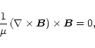
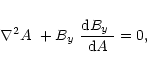
We assume that our coronal structure may be modelled as a force-free
magnetic field satisfying
| (2) |
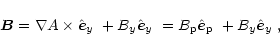
Let us consider a two-dimensional equilibrium in which the plasma and
field variables do not vary along the y-axis
of a Cartesian frame x, y, z. Then, the
equilibrium magnetic field can be written as
Since we are neglecting gas pressure and gravity terms in the
force-balance equation, the density does not appear in Eq. (4) and
one can impose the equilibrium density or Alfvén speed profiles arbitrarily.
In our general two-dimensional equilibrium the density will be given
by a function of the form
![]() ,
which defines the Alfvén speed
by means of
,
which defines the Alfvén speed
by means of
![]() .
.
In this section the equations of linear, ideal MHD waves are derived
for our general, two-dimensional force-free equilibrium.
Let us start with the ideal, cold plasma
MHD equations for adiabatic changes of state,
 |
(8) |
If we now consider small
displacements about the equilibrium state, and assuming time variations of
the form
![]() ,
with
,
with ![]() the frequency,
Eqs. (5)-(7) can be written
in the following form
the frequency,
Eqs. (5)-(7) can be written
in the following form
Equation (12) is a vector formula that actually corresponds to three
second-order partial differential equations for the three velocity
components. Here, the different vectors (and not just ![]() )
have been
decomposed in their components by projecting them onto the directions
defined at each point by the unit vectors,
)
have been
decomposed in their components by projecting them onto the directions
defined at each point by the unit vectors,
![]() (normal to
magnetic surfaces),
(normal to
magnetic surfaces),
![]() (parallel to field lines) and
(parallel to field lines) and
![]() (tangent to magnetic surfaces and perpendicular
to field lines).
A representation of these three basis vectors for a particular magnetic
configuration can be seen in Fig. 1.
Then, any vector, and in particular the velocity perturbation, can be
written as
(tangent to magnetic surfaces and perpendicular
to field lines).
A representation of these three basis vectors for a particular magnetic
configuration can be seen in Fig. 1.
Then, any vector, and in particular the velocity perturbation, can be
written as
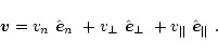 |
(15) |
![\begin{figure}
\par\includegraphics[width=6cm,clip]{ms10167f1.eps}\par\par\end{figure}](/articles/aa/full/2001/15/aa10167/img90.gif) |
Figure 1:
Three dimensional view of magnetic field lines (solid) in a
force-free coronal arcade with uniform shear. Dashed lines are the
projections of field lines onto the xy- and xz-planes. The
field related vectors
|
| Open with DEXTER | |
Once the velocity of the plasma motions has been calculated a task that is performed numerically as explained in Sect. 3, the perturbations to the other physical quantities and forces can be computed. These quantities are given in Appendix C.
The derivation of our main formule are now complete, but we can check to detect the possible presence of errors in the derivation and/or
in the transcription of equations to the numerical code. First, take Eq. (10) and multiply it by
![]() ,
such as
was done before in the process of deriving Eqs. (16) and
(17).
After expressing the perturbed Lorentz force as the sum of the perturbed
pressure gradient and magnetic tension we have
,
such as
was done before in the process of deriving Eqs. (16) and
(17).
After expressing the perturbed Lorentz force as the sum of the perturbed
pressure gradient and magnetic tension we have
 |
(18) |
By considering the normal component of this expression, one can confirm
that the right-hand side of Eq. (16) coincides with the sum of
Eqs. (C.8) and (C.20). Similarly, for the perpendicular component,
the right-hand side of Eq. (17) coincides
with the sum of Eqs. (C.9) and (C.21). And finally, the
sum of Eqs. (C.10) and (C.22) is zero, so
![]() is recovered.
is recovered.
This section is devoted to describing the numerical procedure used in solving Eqs. (16) and (17).
The derivatives of the velocity components in Eqs. (16)
and (17) have been written as combinations of the operators
![]() and
and
![]() .
For the numerical
integration of the wave equations it will be necessary to write these
operators explicitly in terms of partial derivatives in the directions
defined by two spatial coordinates, for which the symbols
.
For the numerical
integration of the wave equations it will be necessary to write these
operators explicitly in terms of partial derivatives in the directions
defined by two spatial coordinates, for which the symbols ![]() and
and
![]() are used, which
are functions of x and z and map the part of the xz-plane in
which the numerical solution is to be computed. Examples of how to
choose these two coordinates as functions of x and z are given
in Sect. 4.
are used, which
are functions of x and z and map the part of the xz-plane in
which the numerical solution is to be computed. Examples of how to
choose these two coordinates as functions of x and z are given
in Sect. 4.
Now, the operators
 |
(19) |
 |
(20) |
can be transformed, with the help of the chain rule, into operators
with derivatives of ![]() and
and ![]() instead of x
and z (see Appendix D).
instead of x
and z (see Appendix D).
The possibility of using coordinates other than x and
z can be of interest in a number of cases. One can, for
example, choose flux coordinates (linked to the shape of
magnetic surfaces) to investigate the Alfvén continuum,
while selecting Cartesian coordinates may be used to study
the discrete fast and Alfvén modes of the system. On the
other hand, cylindrical coordinates
can also be imposed for an equilibrium with longitudinal
invariance such as the one assumed here. It will suffice to
interchange the names for the y- and z-axes and to
express r and ![]() as functions of the poloidal
coordinates x and z.
as functions of the poloidal
coordinates x and z.
One can now insert the equations for the operators
![]() ,
,
![]() ,
etc. from Appendix D into Eqs. (16)
and (17), which results in the following two partial
differential equations with non-constant and complex coefficients,
,
etc. from Appendix D into Eqs. (16)
and (17), which results in the following two partial
differential equations with non-constant and complex coefficients,
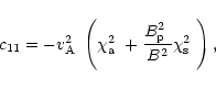
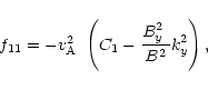
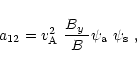
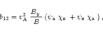
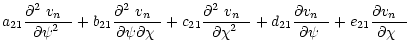
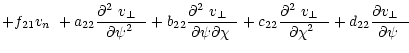
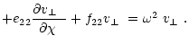
Expressions for the coefficients a11, b11, ... are given in Appendix D.
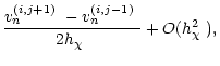
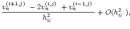
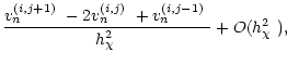
We now construct a finite difference replacement of Eqs.
(21) and (22). The region to be considered is a
rectangle with sides parallel to the ![]() - and
- and ![]() -axes, covered
by a mesh of
-axes, covered
by a mesh of
![]() points in which
approximations to the functions
points in which
approximations to the functions
![]() and
and
![]() are to be computed. At
the point
are to be computed. At
the point
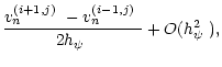
![]() the first and second derivatives of
these functions are approximated in the usual manner
(Mitchell & Griffiths 1980; Ames 1992),
the first and second derivatives of
these functions are approximated in the usual manner
(Mitchell & Griffiths 1980; Ames 1992),
 |
(28) |
Using expressions (23)-(27) to discretise
Eqs. (21) and (22) in the
![]() interior
points yields
interior
points yields
![]() equations for the unknowns at these points and the
equations for the unknowns at these points and the
![]() unknowns at the
points on the boundary of the system. The same discretised equations
can be assumed to apply at the boundary points, but then some boundary
conditions on
unknowns at the
points on the boundary of the system. The same discretised equations
can be assumed to apply at the boundary points, but then some boundary
conditions on
![]() and
and
![]() are needed to eliminate the unknowns that
are introduced by the use of points outside the region of integration.
This issue will be discussed next.
are needed to eliminate the unknowns that
are introduced by the use of points outside the region of integration.
This issue will be discussed next.
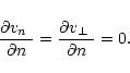
At present, only homogeneous boundary conditions have been implemented
in our numerical code.
Thus, for each of the two velocity components it is possible to choose
between Dirichlet (
![]() or
or
![]() )
or Neumann
(
)
or Neumann
(
![]() or
or
![]() )
conditions. Here
)
conditions. Here
![]() represents the derivative normal to the
boundary, which means that
represents the derivative normal to the
boundary, which means that
![]() on a
on a
![]() boundary and
boundary and
![]() on a
on a
![]() boundary. The first
of these boundary conditions is useful when modelling a boundary that
behaves as a rigid, perfectly
conducting wall, while the second one can be applicable to exploit
spatial symmetry in the solutions, as will be shown in the next section.
boundary. The first
of these boundary conditions is useful when modelling a boundary that
behaves as a rigid, perfectly
conducting wall, while the second one can be applicable to exploit
spatial symmetry in the solutions, as will be shown in the next section.
There are four possible combinations of boundary conditions, namely
The cases given by Eqs. (30), (31) and (32) are a
bit more difficult to handle since the use of the difference equations at
boundary points forces one to introduce fictitious (or "ghost'') points
exterior to the region of integration. Equation (32) poses
little problem since it implies that
![]() and
and
![]() on the
ghost points can be substituted by their counterparts directly
across the boundary. Thus, on the
on the
ghost points can be substituted by their counterparts directly
across the boundary. Thus, on the
![]() boundary Eq. (32)
is equivalent to
boundary Eq. (32)
is equivalent to
![]() ,
which by virtue of Eq. (24) yields
,
which by virtue of Eq. (24) yields
![]() and
and
![]() ,
with the index i=0 indicating fictitious points and
,
with the index i=0 indicating fictitious points and
![]() .
.
Finally, dealing with boundary conditions of the form (30) is
still more complex. Now
![]() is known on the boundary and Eq. (22) needs not be used. However, Eq. (21) discretised on
the boundary contains the values of the two velocity components on
the fictitious points and while
is known on the boundary and Eq. (22) needs not be used. However, Eq. (21) discretised on
the boundary contains the values of the two velocity components on
the fictitious points and while
![]() helps
eliminate the values of
helps
eliminate the values of
![]() outside the computational domain in
favour of values inside the domain, it is not possible to do the
same for
outside the computational domain in
favour of values inside the domain, it is not possible to do the
same for
![]() .
Our approach has been to assume that
.
Our approach has been to assume that
![]() is
antisymmetric about the boundary, so the values of this function
on the ghost mesh points are equal to minus the interior values just
across the boundary. Hence, on the
is
antisymmetric about the boundary, so the values of this function
on the ghost mesh points are equal to minus the interior values just
across the boundary. Hence, on the
![]() boundary Eq. (30)
is interpreted as
boundary Eq. (30)
is interpreted as
![]() and
and
![]() ,
with
,
with
![]() .
.
After discarding the boundary points on which Eqs. (21) and
(22) do not need to be discretised, we are left with a set of
algebraic expressions for the unknowns
![]() and
and
![]() with an additional parameter that must be determined: the frequency
with an additional parameter that must be determined: the frequency
![]() .
This set of equations constitute an eigenvalue problem of the
form
.
This set of equations constitute an eigenvalue problem of the
form
To set up ![]() one must keep in mind that each point on the
two-dimensional grid can be labelled with two indices, i and j,
related to its coordinates
one must keep in mind that each point on the
two-dimensional grid can be labelled with two indices, i and j,
related to its coordinates ![]() and
and ![]() .
It is then necessary
to introduce a way of labelling all points with a single index, k.
To do so, the mesh points are ordered
consecutively, starting from
.
It is then necessary
to introduce a way of labelling all points with a single index, k.
To do so, the mesh points are ordered
consecutively, starting from
![]() ,
next
,
next
![]() ,
etc., until
,
etc., until
![]() .
The next point has coordinates
.
The next point has coordinates
![]() ,
then
,
then
![]() ,
and so on until the point
,
and so on until the point
![]() )
is reached; see Fig.
2 for an example with
)
is reached; see Fig.
2 for an example with ![]() and
and ![]() .
.
![\begin{figure}
\par\includegraphics[width=7cm,clip]{ms10167f2.eps}\par\par\end{figure}](/articles/aa/full/2001/15/aa10167/img170.gif) |
Figure 2:
Mesh points for a finite difference computation with
|
| Open with DEXTER | |
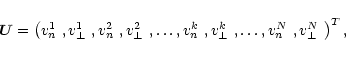
Finally, the unknowns are put together in the vector ![]() constructed as follows
constructed as follows
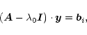
To solve the eigenvalue problem (33) it is important to
keep in mind that ![]() is a large, sparse, non-symmetric matrix and
that common methods used for calculating eigenvalues and/or
eigenvectors of a matrix are computationally expensive. These methods
become impractical when dealing with very large matrices, as in the
present case, in which the size of
is a large, sparse, non-symmetric matrix and
that common methods used for calculating eigenvalues and/or
eigenvectors of a matrix are computationally expensive. These methods
become impractical when dealing with very large matrices, as in the
present case, in which the size of ![]() is of the order of
is of the order of
![]() ,
i.e.
,
i.e.
![]() for
the somewhat moderate values
for
the somewhat moderate values
![]() .
.
The approach chosen here has been to select numerical methods that
exploit the sparseness of ![]() .
First, one can use a coarse grid
to compute selected eigenvectors, e.g. those whose moduli lie between
two values,
.
First, one can use a coarse grid
to compute selected eigenvectors, e.g. those whose moduli lie between
two values,
![]() and
and
![]() .
This task has
been accomplished with the NAG subroutine F02BDF, which first
reduces the complex matrix to Hessenberg form and then makes use of the
LR algorithm and inverse iteration to obtain the desired eigensolutions.
It must be
emphasised that to keep the order of
.
This task has
been accomplished with the NAG subroutine F02BDF, which first
reduces the complex matrix to Hessenberg form and then makes use of the
LR algorithm and inverse iteration to obtain the desired eigensolutions.
It must be
emphasised that to keep the order of ![]() reasonably small the mesh
must be rather coarse (we have used values up to
reasonably small the mesh
must be rather coarse (we have used values up to ![]() and
and
![]() ), since all elements (both zero and non-zero) of the matrix
are stored and this results in large memory requirements. Moreover,
the computational time scales as n3, where
), since all elements (both zero and non-zero) of the matrix
are stored and this results in large memory requirements. Moreover,
the computational time scales as n3, where
![]() as we mentioned before.
as we mentioned before.
At this stage some information has been determined regarding the spectrum of the system, so it is now possible to refine the solutions by using a finer grid together with the frequency values coming from the previous step. For the purpose of obtaining single eigenvalues and their corresponding eigensolution, the inverse iteration has been used. Details of this technique can be found in Kerner (1989) and Press et al. (1992); we have followed the second of these references but in some aspects our implementation is different from theirs and in addition there seems to be an error in their Eq. (11.7.10), we therefore describe our procedure.
Recall that the aim is to obtain an approximation, as accurate as
possible, of an eigensolution of the eigenvalue problem
(33). We start from an initial approximation, ![]() ,
of the desired eigenvalue and construct the matrix
,
of the desired eigenvalue and construct the matrix
![]() ,
with
,
with ![]() the identity matrix. The idea now
is to express
the identity matrix. The idea now
is to express ![]() satisfying Eq. (33) as
satisfying Eq. (33) as
| (35) |
 |
(38) |
| (39) |
| (40) |
 |
(41) |
 |
(42) |
The advantage of the inverse iteration method is that it is
much faster than other methods which calculate all or selected
eigensolutions of ![]() .
Nevertheless, one still must solve a
large algebraic problem (Eq. (36)) a number of times. It is
here that the sparseness of
.
Nevertheless, one still must solve a
large algebraic problem (Eq. (36)) a number of times. It is
here that the sparseness of ![]() can be exploited, since there are
some algorithms that efficiently solve this kind of problem.
One of these algorithms is provided as the package ME48, which
is part of the Harwell Sparse Matrix Library. There is one
subroutine in this
package that first selects permutations
can be exploited, since there are
some algorithms that efficiently solve this kind of problem.
One of these algorithms is provided as the package ME48, which
is part of the Harwell Sparse Matrix Library. There is one
subroutine in this
package that first selects permutations ![]() and
and ![]() so that the matrix
so that the matrix ![]() is in block triangular form and
can thus be easily factorised. Next, a second subroutine
performs the factorisation of each diagonal block and, finally,
a third subroutine solves the system by block solution through
the block triangular form. By far the most time consuming of
these tasks is the matrix factorisation, which must be carried
out only once at the beginning of the iterative process (i.e. for
i=1). The details of the factorisation are stored and in
subsequent steps one can use them to solve Eq. (36) at
a small computational cost.
is in block triangular form and
can thus be easily factorised. Next, a second subroutine
performs the factorisation of each diagonal block and, finally,
a third subroutine solves the system by block solution through
the block triangular form. By far the most time consuming of
these tasks is the matrix factorisation, which must be carried
out only once at the beginning of the iterative process (i.e. for
i=1). The details of the factorisation are stored and in
subsequent steps one can use them to solve Eq. (36) at
a small computational cost.
After solving the eigenvalue problem, Eq. (33), we have
an approximation to the spatial distribution of the functions
![]() and
and
![]() from which the perturbed quantities (density, magnetic field
components and magnetic pressure) and perturbed forces (components of
magnetic pressure gradient and magnetic tension) can be
obtained. We use Eqs. (C.1)-(C.10) and
(C.20)-(C.22) and again write the directional derivatives
as in Appendix D. Next, the derivatives of
from which the perturbed quantities (density, magnetic field
components and magnetic pressure) and perturbed forces (components of
magnetic pressure gradient and magnetic tension) can be
obtained. We use Eqs. (C.1)-(C.10) and
(C.20)-(C.22) and again write the directional derivatives
as in Appendix D. Next, the derivatives of
![]() and
and
![]() in the resulting expressions are approximated by the finite difference
formulas (23)-(27). We have found it very
useful to compute these physical quantities
for they can shed light on how the oscillatory motions are driven and,
therefore, on the nature of the modes.
in the resulting expressions are approximated by the finite difference
formulas (23)-(27). We have found it very
useful to compute these physical quantities
for they can shed light on how the oscillatory motions are driven and,
therefore, on the nature of the modes.
Despite the complexity of the coefficients in Eqs. (21)
and (22), which contain many derivatives of equilibrium
quantities and of the generalised coordinates ![]() and
and ![]() ,
the numerical code is rather simple to use. The end user only
needs to define a few of subroutines, providing details on the
equilibrium (in particular, Bx, By, Bz and
,
the numerical code is rather simple to use. The end user only
needs to define a few of subroutines, providing details on the
equilibrium (in particular, Bx, By, Bz and
![]() as functions
of position) and
also the first- and second-order derivatives of the Cartesian
magnetic field components with respect to x and z. For the
computation of the density perturbation, the first-order derivatives of
as functions
of position) and
also the first- and second-order derivatives of the Cartesian
magnetic field components with respect to x and z. For the
computation of the density perturbation, the first-order derivatives of
![]() with respect to x and z must also be given. Moreover,
if generalised coordinates are to be used instead of the x- and z-coordinates, then the definition of
with respect to x and z must also be given. Moreover,
if generalised coordinates are to be used instead of the x- and z-coordinates, then the definition of ![]() and
and ![]() in terms of x and z must be provided together with their
first- and second-order derivatives.
in terms of x and z must be provided together with their
first- and second-order derivatives.
In this section we analyse numerically the normal modes of oscillation of two magnetic configurations: a uniform, straight magnetic field and a potential arcade. These two cases have analytical or simple numerical solutions so that the goodness of the numerical code can be checked.
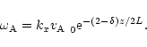
We first consider a cold plasma in a horizontal, straight and uniform
magnetic field
![]() .
The density is given by
.
The density is given by
![]() so that the Alfvén speed is
so that the Alfvén speed is
![]() .
Also, the plasma is assumed
to be contained in a box limited by rigid plates at
.
Also, the plasma is assumed
to be contained in a box limited by rigid plates at ![]() and
z=0, H, which corresponds to Dirichlet boundary conditions for
and
z=0, H, which corresponds to Dirichlet boundary conditions for
![]() and
and
![]() on the edges of the computational domain.
on the edges of the computational domain.
The wave Eqs. (16) and (17) reduce to
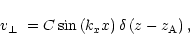
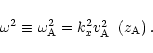
Equation (44) describes Alfvén continuum modes.
The continuous part of the MHD wave spectrum is well documented in the
plasma physics literature (see e.g. Appert 1974; Goedbloed
1975, 1983) and
distribution theory yields a solution to Eq. (44) in terms
of the delta function
![]() ,
where
,
where
![]() is the
singular surface, multiplied by a function
of x. After imposing the vanishing of
is the
singular surface, multiplied by a function
of x. After imposing the vanishing of
![]() at
at ![]() we obtain
we obtain
![\begin{figure}
\par\subfigure[]{\includegraphics[width=5.5cm,clip]{ms10167f3a.ep...
...gure[]{\includegraphics[width=6.3cm,clip]{ms10167f3b.eps} }
\par\par\end{figure}](/articles/aa/full/2001/15/aa10167/img226.gif) |
Figure 3:
a) Surface plot of the perpendicular velocity component
for the Alfvén fundamental continuum mode
in a uniform, straight magnetic field configuration ( |
| Open with DEXTER | |
 |
(47) |
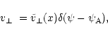
Continuum solutions, like the one shown in Fig. 3a, are
characterised by
![]() (to an extremely high accuracy) in the
whole computational domain and
(to an extremely high accuracy) in the
whole computational domain and
![]() everywhere except on a
single magnetic surface. Therefore, our numerical code recovers the
delta function in the analytical solution (45) by renormalising
the numerical eigenfunctions in such a way that finite values of
everywhere except on a
single magnetic surface. Therefore, our numerical code recovers the
delta function in the analytical solution (45) by renormalising
the numerical eigenfunctions in such a way that finite values of
![]() outside the singular surface and of
outside the singular surface and of
![]() everywhere become zero and
infinite values of
everywhere become zero and
infinite values of
![]() on the singular surface become finite. To
confirm the coincidence between the numerical and analytical solutions
we have plotted them together in Fig. 3b, that shows a
perfect agreement.
on the singular surface become finite. To
confirm the coincidence between the numerical and analytical solutions
we have plotted them together in Fig. 3b, that shows a
perfect agreement.
Finally, the Alfvén continuous spectrum has been computed numerically and
compared with the analytical formula (48). The
results, displayed in
Fig. 4, again show an excellent agreement.
![\begin{figure}
\par\includegraphics[width=6.2cm,clip]{ms10167f4.eps}\par\par\end{figure}](/articles/aa/full/2001/15/aa10167/img237.gif) |
Figure 4:
Plot of Alfvén continuum frequency, |
| Open with DEXTER | |
 |
(51) |
 |
(52) |
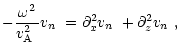
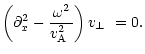
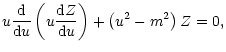
For the vertical dependence of the normal velocity we obtain a second-order
ordinary differential equation,
 |
(57) |
 |
(61) |
![\begin{figure}
\par\subfigure[]{\includegraphics[width=5.5cm,clip]{ms10167f5a.ep...
...gure[]{\includegraphics[width=5.8cm,clip]{ms10167f5b.eps} }
\par\par\end{figure}](/articles/aa/full/2001/15/aa10167/img258.gif) |
Figure 5:
a) Surface plot of the normal velocity component for the
fundamental (i.e., nx=1, nz=1) fast mode
in a straight magnetic field with |
| Open with DEXTER | |
A numerical solution has been computed for a ![]() ,
H/L=4
configuration (see
Fig. 5a) using
,
H/L=4
configuration (see
Fig. 5a) using ![]() and
and ![]() given
by Eqs. (49) and (50). This mode has
given
by Eqs. (49) and (50). This mode has
![]() and
and
![]() (within machine precision), such as
corresponds to a fast mode, and a close inspection reveals
(within machine precision), such as
corresponds to a fast mode, and a close inspection reveals
![]() is a
separable function of x and z. Since
is a
separable function of x and z. Since
![]() displays a single
extrema in the z-direction we label this as a nz=1 mode.
A comparison between the z-dependence of this numerical solution and
the analytical one
is shown in Fig. 5b, which displays the fine performance
of the numerical code.
displays a single
extrema in the z-direction we label this as a nz=1 mode.
A comparison between the z-dependence of this numerical solution and
the analytical one
is shown in Fig. 5b, which displays the fine performance
of the numerical code.
The last check we perform with the straight magnetic field configuration
consists in comparing the numerical frequency for various fast modes with
the solutions calculated from Eq. (60); see Fig. 6. As expected, the two sets of frequencies agree
quite well, the larger difference appearing for modes with higher spatial
structure (that is, with larger values of nx and/or nz) for which a
finer grid is required to achieve an accuracy similar to that of smoother
modes.
![\begin{figure}
\par\includegraphics[width=6.2cm,clip]{ms10167f6.eps}\par\par\end{figure}](/articles/aa/full/2001/15/aa10167/img260.gif) |
Figure 6:
Comparison of fast mode frequencies in a uniform, straight
magnetic field configuration with |
| Open with DEXTER | |
Another particular solution of the force-free Eq. (1)
is a potential structure such as a coronal arcade of magnetic field lines
(see Fig. 7)
with
![]() and a flux function of the form
and a flux function of the form
 |
(63) |
![\begin{figure}
\par\includegraphics[width=5.7cm,clip]{ms10167f7.eps}\par\par\end{figure}](/articles/aa/full/2001/15/aa10167/img268.gif) |
Figure 7:
Magnetic field lines in a coronal potential arcade with a
flux function given by Eq. (62). The field related
vectors
|
| Open with DEXTER | |
The MHD modes of oscillation of this potential arcade were investigated by
Terradas et al. (1999) and by Oliver et al. (1993), who
wrote the linear ideal MHD wave
equations for this zero-![]() configuration as follows
configuration as follows
Equation (65) describes the Alfvén mode, characterised by plasma
displacements in the perpendicular direction, i.e. along the y-axis.
The
![]() derivative makes this mode highly anisotropic and
motions are confined to a particular magnetic surface (described by
A=constant). Hence, solutions to Eq. (65) are of the
form
derivative makes this mode highly anisotropic and
motions are confined to a particular magnetic surface (described by
A=constant). Hence, solutions to Eq. (65) are of the
form
![\begin{figure}
\par\subfigure[]{\includegraphics[width=5.5cm,clip]{ms10167f8a.ep...
...gure[]{\includegraphics[width=5.7cm,clip]{ms10167f8b.eps} }
\par\par\end{figure}](/articles/aa/full/2001/15/aa10167/img277.gif) |
Figure 8:
a) Surface plot of the perpendicular velocity component
for the Alfvén fundamental continuum mode
in a potential arcade with |
| Open with DEXTER | |
![\begin{figure}
\par\includegraphics[width=6.3cm,clip]{ms10167f9.eps}\par\par\end{figure}](/articles/aa/full/2001/15/aa10167/img278.gif) |
Figure 9:
Plot of the frequency, |
| Open with DEXTER | |
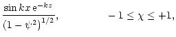
In order to obtain
![]() ,
Oliver et al. (1993) considered
a particular field line whose footpoints have coordinates
,
Oliver et al. (1993) considered
a particular field line whose footpoints have coordinates ![]() ,
z=0. The directional derivative
,
z=0. The directional derivative
![]() along this field
line can be written as
along this field
line can be written as
 |
(67) |
 |
(69) |
For the numerical computations we have considered the case ![]() and
have chosen generalised coordinates that facilitate the
recovery of continuum modes. By selecting
and
have chosen generalised coordinates that facilitate the
recovery of continuum modes. By selecting
Numerical solutions have been found by solving Eqs. (16) and
(17) in a mesh with
![]() ,
,
![]() points. The eigenfunction plotted in Fig. 8a possesses, as
expected,
points. The eigenfunction plotted in Fig. 8a possesses, as
expected,
![]() on the whole system and
on the whole system and
![]() except on a
singular surface
except on a
singular surface
![]() .
Using Eqs. (70) and (71)
one can express
.
Using Eqs. (70) and (71)
one can express ![]() in terms of x on the singular surface,
in terms of x on the singular surface,
Changing the position of the field line footpoint, x0, produces a
variation of the mode frequency that generates the Alfvén continuous
spectrum.
Figure 9 shows the frequency of the fundamental Alfvén
continuum mode versus the footpoint position, with the numerical values
fitting well the
results of Oliver et al. (1993).
![\begin{figure}
\par\subfigure[]{\includegraphics[width=5.8cm,clip]{ms10167f10a.e...
...ure[]{\includegraphics[width=5.8cm,clip]{ms10167f10b.eps} }
\par\par\end{figure}](/articles/aa/full/2001/15/aa10167/img292.gif) |
Figure 10:
a) Surface plot of
|
| Open with DEXTER | |
|
(74) |
For the vertical dependence a second-order
differential equation similar to the one for the straight field
(Eq. (53)) is obtained,
![\begin{displaymath}%
\frac{{\rm d}^2Z}{{\rm d}z^2}+
\left[\frac{\omega^2}{\mbox{...
...{0}^2}\,{\rm e}^{-k\left(\delta-2\right)z}
-k_{x}^2\right]Z=0.
\end{displaymath}](/articles/aa/full/2001/15/aa10167/img295.gif) |
(75) |
Numerical solutions have been computed for a potential arcade configuration
with ![]() and H/L=4.
Eqs. (16) and (17) are now solved in a Cartesian mesh with
and H/L=4.
Eqs. (16) and (17) are now solved in a Cartesian mesh with
![]() and
and
![]() and
and
![]() points in the x- and z-directions. Figure 10a shows a surface plot
of
points in the x- and z-directions. Figure 10a shows a surface plot
of
![]() for the nx=2, nz=1 fast mode (which, as all other fast
modes in this configuration, have
for the nx=2, nz=1 fast mode (which, as all other fast
modes in this configuration, have
![]() ).
As can be seen, the spatial structure of the eigenfunction appears to be a
separable function of the x and z variables, as was assumed by
Oliver et al. (1993)
in obtaining analytical solutions to the wave Eq. (73).
).
As can be seen, the spatial structure of the eigenfunction appears to be a
separable function of the x and z variables, as was assumed by
Oliver et al. (1993)
in obtaining analytical solutions to the wave Eq. (73).
![\begin{figure}
\par\includegraphics[width=5.7cm,clip]{ms10167f11.eps}\par\par\end{figure}](/articles/aa/full/2001/15/aa10167/img298.gif) |
Figure 11:
Comparison of fast mode frequencies in a potential arcade
with |
| Open with DEXTER | |
Figures 10b and 11 show the perfect agreement between the numerical and analytical solutions in both the spatial structure of the eigenfunctions as well as in the values of the wave frequencies. The agreement between the two sets of solutions in Fig. 11 is better for modes with low frequency and with few spatial oscillations in the xz-domain.
In this paper, the linearised MHD wave equations for a two-dimensional force-free magnetic field, having longitudinal invariance, have been derived and a numerical code to solve the resulting system of coupled partial differential equations has been introduced. Two simple magnetic configurations (a straight magnetic field and a potential arcade), having analytical or simple numerical solutions, have been used to test the goodness and accuracy of the code, and the comparison of the results points out an excellent agreement. The code also proves to be a good tool for the investigation of Alfvén continuum modes in two-dimensional equilibria, which are obtained by selecting flux coordinates instead of Cartesian coordinates. Of course, the code can be used to study linear waves in more complex force-free fields and our aim is to use it to investigate linear MHD waves in sheared coronal magnetic arcades. In these structures, the longitudinal component of the magnetic field as well as the longitudinal wavenumber will produce the coupling of fast and Alfvén modes, changing substantially the spatial structure of the perturbed physical quantities in such a way that modes can possess both fast and Alfvén mode properties. Also, in the case of a curved magnetic field, curvature will introduce extra effects worth being studied.
Despite the complexity of Eqs. (16) and (17), the numerical code is simple to use since the various quantities coming into the wave equations (like the coefficients presented in Appendices B and D) are computed from subroutines provided by the user in which the equilibrium variables and their (first- and/or second-order) derivatives are specified. In addition, the possibility of using different coordinate systems, apart from the Cartesian ones, allows the oscillatory modes of different equilibrium configurations to be explored. Finally, the output of the code consists not only of the normal and perpendicular velocity components, but also the perturbed density and the three components of the perturbed magnetic tension and perturbed magnetic pressure gradient. All this information will be helpful when investigating the physical nature of coupled fast and Alfvén modes.
Acknowledgements
I. A. acknowledges DGES for a fellowship. The authors wish to acknowledge the financial support received from DGES under project PB96-0092.
In this appendix, a detailed derivation of the wave Eqs. (16)
and (17) is presented. To make progress with Eq. (12)
some expressions are needed. First, the curl of the equilibrium magnetic field
is given by
 |
(A.1) |
Next, the curl and divergence of the basis vectors can be determined,
The following short-hand notation for the derivatives of the equilibrium
(total and poloidal) magnetic field strength are used
| C1 | = |  |
(B.13) |
| C2 | = | (B.14) | |
| C3 | = |  |
|
| (B.15) | |||
| C4 | = |  |
|
| (B.16) |
| g1 | = |  |
(B.17) |
| g2 | = |  |
(B.18) |
| g3 | = | (B.19) |
![$\displaystyle %
g_{\rm 1s}=\frac{B}{\mbox{$B_{\rm p}$ }}\frac{{\rm d}\mbox{$B_{...
...eft(B\mbox{$B_{\rm s}$ }-\mbox{$B_{\rm p}$ }\mbox{$B_{\rm ps}$ }\right)\right],$](/articles/aa/full/2001/15/aa10167/img354.gif) |
(B.20) |
 |
(B.21) |
![$\displaystyle \frac{\mbox{$B^2_{\rm p}$ }-\mbox{$B^2_{y}$ }}{\mbox{$B^2_{\rm p}...
...ht]
+ \frac{B^4\mbox{$B_{\rm a}$ }\mbox{$B_{\rm ps}$ }}{\mbox{$B^3_{\rm p}$ }},$](/articles/aa/full/2001/15/aa10167/img357.gif) |
(B.22) |
 |
(B.23) |
| (B.24) |
| = |  |
(C.2) |
| = |  |
(C.3) |
| = | ![$\displaystyle -\frac{1}{\mbox{$B_{\rm p}$ }}\mbox{$\left(\mbox{$\nabla A$ }\cdo...
...rm s}$ }+\mbox{$B_{\rm p}$ }\mbox{$B_{\rm ps}$ }\right)\right]\mbox{$v_\perp$ }$](/articles/aa/full/2001/15/aa10167/img366.gif) |
(C.4) |
| = | (C.6) | ||
| = | (C.7) |
| h1 | = | (C.23) | |
| h2 | = | (C.24) | |
| h3 | = | (C.25) | |
| h4 | = | (C.26) | |
| h5 | = | (C.27) | |
| h6 | = | (C.28) | |
| h7 | = | 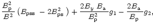 |
(C.29) |
| h8 | = | 0, | (C.30) |
| h9 | = | |
|
| (C.31) | |||
| h10 | = | ||
| (C.32) | |||
| h11 | = | (C.33) | |
| h12 | = | (C.34) |
| = |  |
(D.1) | |
| = |  |
(D.2) |
 |
(D.3) |
 |
(D.4) |
 |
(D.5) |
| = | (D.7) | ||
| = | (D.8) | ||
| = | (D.9) | ||
| = | (D.10) | ||
| = | (D.11) | ||
| = | (D.12) |
Finally, the expressions for the coefficients in Eqs. (21) and
(22) are given by
 |
(D.14) |
 |
(D.15) |
![$\displaystyle d_{11}=-\mbox{$v^2_{\rm A}$ }\left\{\mbox{$\psi_{\rm aa}$ }+\frac...
...box{$B_{\rm a}$ }}{\mbox{$B^3_{\rm p}$ }}\right]\mbox{$\psi_{\rm a}$ }\right\},$](/articles/aa/full/2001/15/aa10167/img479.gif) |
(D.16) |
![$\displaystyle e_{11}=-\mbox{$v^2_{\rm A}$ }\left\{\mbox{$\chi_{\rm aa}$ }+\frac...
...ox{$B_{\rm a}$ }}{\mbox{$B^3_{\rm p}$ }}
\right]\mbox{$\chi_{\rm a}$ }\right\},$](/articles/aa/full/2001/15/aa10167/img480.gif) |
(D.17) |
 |
(D.18) |
 |
(D.19) |
 |
(D.20) |
 |
(D.21) |
![$\displaystyle d_{12}=-\mbox{$v^2_{\rm A}$ }\left\{-\frac{\mbox{$B_{y}$ }}{B}\mb...
...{$B_{\rm p}$ }\mbox{$B_{\rm pa}$ }\right)\right]\mbox{$\psi_{\rm s}$ }\right\},$](/articles/aa/full/2001/15/aa10167/img485.gif) |
(D.22) |
![$\displaystyle e_{12}=-\mbox{$v^2_{\rm A}$ }\left\{-\frac{\mbox{$B_{y}$ }}{B}\mb...
...{$B_{\rm p}$ }\mbox{$B_{\rm pa}$ }\right)\right]\mbox{$\chi_{\rm s}$ }\right\},$](/articles/aa/full/2001/15/aa10167/img486.gif) |
(D.23) |
![$\displaystyle f_{12}=-\mbox{$v^2_{\rm A}$ }\left\{C_{2}-\left[\frac{1}{B}\left(...
...x{$B^2_{y}$ }\mbox{$B_{\rm a}$ }}{\mbox{$B^2_{\rm p}$ }}\right]i k_{y}\right\},$](/articles/aa/full/2001/15/aa10167/img487.gif) |
(D.24) |
 |
(D.25) |
 |
(D.26) |
 |
(D.27) |
![$\displaystyle d_{21}=-\mbox{$v^2_{\rm A}$ }\left[-\frac{\mbox{$B_{y}$ }}{B}\mbo...
...$ }B^2\mbox{$B_{\rm a}$ }}{\mbox{$B^3_{\rm p}$ }}\mbox{$\psi_{\rm s}$ }\right],$](/articles/aa/full/2001/15/aa10167/img491.gif) |
(D.28) |
e21=![$\displaystyle -\mbox{$v^2_{\rm A}$ }\left[-\frac{\mbox{$B_{y}$ }}{B}\mbox{$\chi...
...$ }B^2\mbox{$B_{\rm a}$ }}{\mbox{$B^3_{\rm p}$ }}\mbox{$\chi_{\rm s}$ }\right],$](/articles/aa/full/2001/15/aa10167/img492.gif) |
(D.29) |
 |
(D.30) |
 |
(D.31) |
 |
(D.32) |
 |
(D.33) |
 |
(D.34) |
 |
(D.35) |


![$\displaystyle \frac{1}{\mbox{$B^2_{\rm p}$ }}\mbox{$\left(\mbox{$\nabla A$ }\cd...
... p}$ }}\right]\mbox{$\left(\mbox{$\nabla A$ }\cdot\nabla\right)$ }\mbox{$v_n$ }$](/articles/aa/full/2001/15/aa10167/img77.gif)
![$\displaystyle +\left(C_{1}-
\frac{\mbox{$B^2_{y}$ }}{B^2}k_y^2\right)\mbox{$v_n...
...ht)\right]\mbox{$\left(\mbox{$\nabla A$ }\cdot\nabla\right)$ }\mbox{$v_\perp$ }$](/articles/aa/full/2001/15/aa10167/img78.gif)
![$\displaystyle -\left[\frac{1}{B}\frac{{\rm d}\mbox{$B_{y}$ }}{{\rm d}A}+\frac{\...
...box{$B_{\rm a}$ }}{\mbox{$B^2_{\rm p}$ }}
\right]ik_y\right\}\mbox{$v_\perp$ },$](/articles/aa/full/2001/15/aa10167/img79.gif)


![\begin{displaymath}
%
\frac{{\rm d}^2 Z}{{\rm d}z^2}+\left[\frac{\omega^2}{\mbox{$v^2_{\rm A}$ }\left(z\right)}-k_{x}^2\right]
Z=0.
\end{displaymath}](/articles/aa/full/2001/15/aa10167/img243.gif)
![\begin{displaymath}
%
\frac{{\rm d}^2\tilde v_\perp}{{\rm d}x^2}
+\frac{\omega^2...
...{\cos kx}\right]^{\delta}
\cos^{-2} kx_{0}\,\,\tilde v_\perp=0
\end{displaymath}](/articles/aa/full/2001/15/aa10167/img282.gif)


![$\displaystyle -\frac{1}{\mbox{$B_{\rm p}$ }}\mbox{$\left(\mbox{$\nabla A$ }\cdo...
..._{\rm ps}$ }\right)
-\frac{\mbox{$B_{\rm p}$ }}{B}ik_y\right]\mbox{$v_\perp$ }.$](/articles/aa/full/2001/15/aa10167/img368.gif)
![$\displaystyle +\left.\frac{\left(\mbox{$B^2_{\rm p}$ }-\mbox{$B^2_{y}$ }\right)...
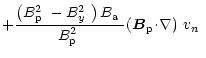
... p}$ }}\right]\mbox{$\left(\mbox{$\nabla A$ }\cdot\nabla\right)$ }\mbox{$v_n$ }$](/articles/aa/full/2001/15/aa10167/img382.gif)

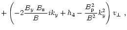
![$\displaystyle + \left[\frac{1}{B}\left(B\mbox{$B_{\rm a}$ }+\mbox{$B_{\rm p}$ }\mbox{$B_{\rm pa}$ }\right)ik_y+h_{2}\right]\mbox{$v_\perp$ },$](/articles/aa/full/2001/15/aa10167/img386.gif)
![$\displaystyle + \left[\frac{1}{B}\ ik_y-\frac{\mbox{$B_{y}$ }}{B\mbox{$B^2_{\rm...
...\right)\right]\mbox{$\left(\mbox{$\nabla A$ }\cdot\nabla\right)$ }\mbox{$v_n$ }$](/articles/aa/full/2001/15/aa10167/img390.gif)
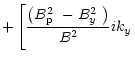
![$\displaystyle + \left[\frac{\left(\mbox{$B^2_{\rm p}$ }-\mbox{$B^2_{y}$ }\right)\mbox{$B_{\rm a}$ }}{\mbox{$B^2_{\rm p}$ }}ik_y + h_{3}\right]\mbox{$v_n$ }$](/articles/aa/full/2001/15/aa10167/img391.gif)
![$\displaystyle + \left[\frac{\left(\mbox{$B^2_{\rm p}$ }-\mbox{$B^2_{y}$ }\right...
...rm a}$ }\mbox{$B_{y}$ }}{\mbox{$B^3_{\rm p}$ }}ik_y + h_{5}\right]\mbox{$v_n$ }$](/articles/aa/full/2001/15/aa10167/img401.gif)
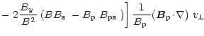
![$\displaystyle -\left.\frac{\mbox{$B_{\rm p}$ }}{B^2}
\left(B\mbox{$B_{\rm s}$ }...
...mbox{$B_{\rm ps}$ }\right)\right]ik_y\mbox{$v_\perp$ }
+h_{6}\mbox{$v_\perp$ }.$](/articles/aa/full/2001/15/aa10167/img406.gif)
![$\displaystyle - \left[\frac{\left(\mbox{$B^2_{\rm p}$ }-\mbox{$B^2_{y}$ }\right...
...m a}$ }\mbox{$B_{y}$ }}{\mbox{$B^3_{\rm p}$ }}ik_y + h_{11}\right]\mbox{$v_n$ }$](/articles/aa/full/2001/15/aa10167/img437.gif)
![$\displaystyle -\left.\frac{\mbox{$B_{\rm p}$ }}{B^2}
\left(B\mbox{$B_{\rm s}$ }...
...box{$B_{\rm ps}$ }\right)\right]ik_y\mbox{$v_\perp$ }
+h_{12}\mbox{$v_\perp$ }.$](/articles/aa/full/2001/15/aa10167/img441.gif)