Fig. 13.
Download original image
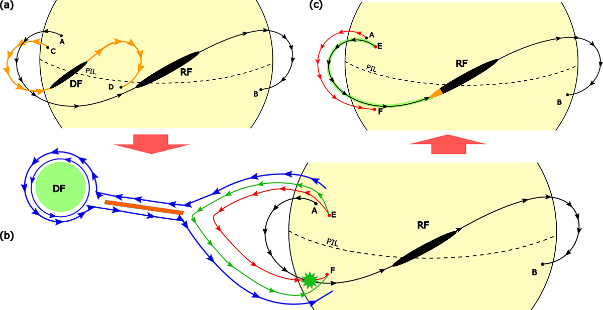
Potential mechanism for energy transfer from solar flare to filament. In panel (a), the pre-eruptive state on 14 March after the jet1 is shown. The solid black line represents the field lines for the RF segment, whereas the orange line represents the field of the DF segment. Both segments are represented by black ellipsoids. The dashed line is the PIL. In panel (b), the DF eruption (green circle) and its magnetic structure (blue lines) are represented. The orange band is the reconnection zone under the erupted filament according to the CSHKP model. The green and blue lines represent the same field line in different phases. Both connect the points E and F. The green one is newly reconnected in the current layer of the orange band; it contracts and forms the red line. In this contraction, it reconnects with the line of the filament channel AB. The region where they reconnect is marked by a green star. In the post-reconnection evolution (c), the change in magnetic field line connectivity is observed. The filament’s original foot point A shifts to E, forming a new foot point, EB, and a post-flare loop, AF. Hot plasma transferred from the flare is represented by the greenish region east of the EB line, while the orange area on the filament indicates the subsequent brightening.
Current usage metrics show cumulative count of Article Views (full-text article views including HTML views, PDF and ePub downloads, according to the available data) and Abstracts Views on Vision4Press platform.
Data correspond to usage on the plateform after 2015. The current usage metrics is available 48-96 hours after online publication and is updated daily on week days.
Initial download of the metrics may take a while.