Fig. 9
Download original image
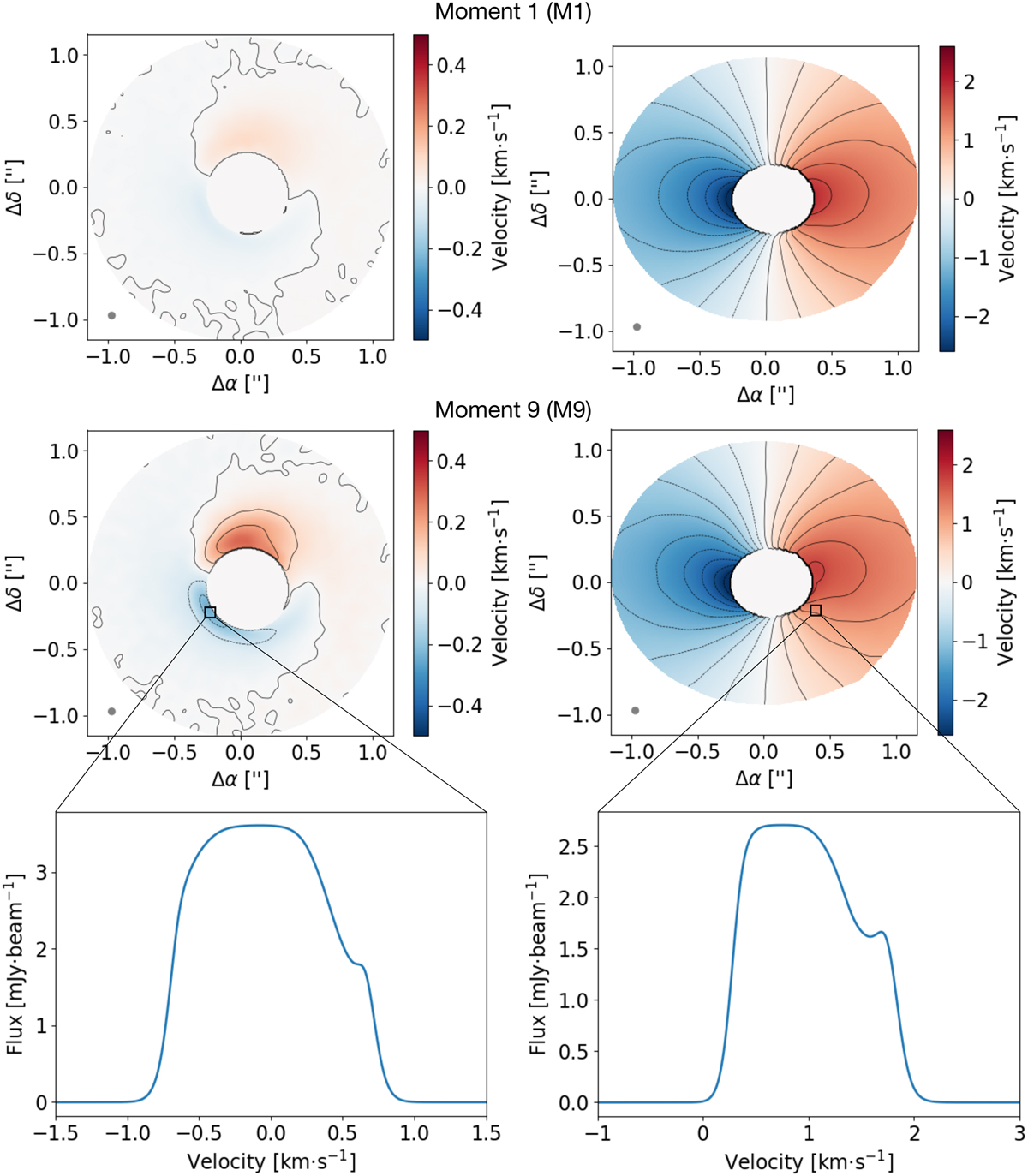
Moment maps from the RT simulations. Top panels: Moment 1 maps from Monte Carlo radiative transfer simulations i = 0° (left) and i = 30° (right). The grey circle in the bottom left corner represents the corresponding beam size. Middle panels: Moment 9 maps, again obtained from the Monte Carlo radiative transfer of the simulation dump, i = 0° (left) and i = 30° (right). Bottom panels: Brightness-velocity maps, i = 0° (left) and i = 30° (right), for selected pixels for highlighting the large span of different velocity contributions in individual pixels. The maps are obtained after convolving spatially the image with a Gaussian beam of Δs = 0.05 arcsec (marked as a grey circle in the bottom left corner of each image) and Δυ = 0.05 km s−1. We note that the convention about velocities in observations is that blue-shift of lines is associated with negative velocities, while red-shift is associated with positive velocities – for example, this implies that υz in this plot is opposite in sign with respect to that in Fig. 7. The case i = 0° shows well how M1 maps tend to underestimate the vertical velocity contribution compared to M9 maps.
Current usage metrics show cumulative count of Article Views (full-text article views including HTML views, PDF and ePub downloads, according to the available data) and Abstracts Views on Vision4Press platform.
Data correspond to usage on the plateform after 2015. The current usage metrics is available 48-96 hours after online publication and is updated daily on week days.
Initial download of the metrics may take a while.