| Issue |
A&A
Volume 680, December 2023
|
|
|---|---|---|
| Article Number | A43 | |
| Number of page(s) | 22 | |
| Section | Interstellar and circumstellar matter | |
| DOI | https://doi.org/10.1051/0004-6361/202347288 | |
| Published online | 06 December 2023 | |
Initial conditions of star formation at ≲2000 au: Physical structure and NH3 depletion of three early-stage cores
1
Max-Planck-Institut für Extraterrestrische Physik,
Giessenbachstr. 1,
85748
Garching bei München, Germany
e-mail: ylin@mpe.mpg.de
2
Department of Physics,
PO Box 64,
University of Helsinki,
00014
Helsinki, Finland
3
Green Bank Observatory,
PO Box 2,
Green Bank,
WV
24944,
USA
4
National Astronomical Observatories, Chinese Academy of Sciences,
Beijing
100101, PR China
5
Department of Physics, National Sun Yat-Sen University,
No. 70, Lien-Hai Road,
Kaohsiung City
80424,
Taiwan,
ROC
Received:
26
June
2023
Accepted:
22
August
2023
Context. Pre-stellar cores represent a critical evolutionary phase in low-mass star formation. Characterisations of the physical conditions of pre-stellar cores provide important constraints on star and planet formation theory and are pre-requisites for establishing the dynamical evolution and the related chemical processes.
Aims. We aim to unveil the detailed thermal structure and density distribution of three early-stage cores -starless core L1517B and pre-stellar cores L694-2 and L429- with the high angular resolution observations of the NH3 (1,1) and (2,2) inversion transitions obtained with VLA and GBT. In addition, we explored if and where NH3 depletes in the central regions of the cores.
Methods. We calculated the physical parameter maps of gas kinetic temperature, NH3 column density, line width, and centroid velocity of the three cores utilising the NH3 (1,1) and (2,2) lines. We applied the mid-infrared extinction method to the Spitzer 8 μm map to obtain a high angular resolution hydrogen column density map. We examined the correlation between the derived parameters and the properties of individual cores. We derived the gas density profile from the column density maps and assessed the variation of NH3 abundance as a function of gas volume density.
Results. The measured temperature profiles of the cores L429 and L1517B show a minor decrease towards the core centre, dropping from ~9 K to below 8 K, and ~11 K to 10 K, while L694-2 has a rather uniform temperature distribution of ~9 K. Among the three cores, L429 has the highest central gas density, close to sonic velocity line width, and the largest localised velocity gradient, all indicative of an advanced evolutionary stage. We resolve that the abundance of NH3 becomes two times lower in the central region of L429, occurring around a (line-of-sight mass-averaged) gas density of 4.4 × 104 cm−3. Compared to Ophiuchus/H-MM1 which shows an even stronger drop of the NH3 abundance at 2 × 105 cm−3, the abundance variations of the three cores plus Ophiuchus/H-MM1 suggest a progressive NH3 depletion with increasing central density in pre-stellar cores.
Key words: astrochemistry / ISM: abundances / dust, extinction / evolution / ISM: structure / ISM: clouds
© The Authors 2023
 Open Access article, published by EDP Sciences, under the terms of the Creative Commons Attribution License (https://creativecommons.org/licenses/by/4.0), which permits unrestricted use, distribution, and reproduction in any medium, provided the original work is properly cited.
This article is published in open access under the Subscribe to Open model.
Open Access funding provided by Max Planck Society.
1 Introduction
Pre-stellar cores represent a critical stage in the process of low-mass star formation: the molecular gas has reached adequate density for self-gravity to balance or even surpass the outward forces (thermal and turbulent pressure, rotation, and magnetic field; see e.g. Myers & Benson 1983; Bergin & Tafalla 2007; Pineda et al. 2023). Compared to its prior stage of starless cores, these cores are denser and on the verge of forming protostars. The significance of studying the physical conditions of pre-stellar cores is twofold: (1) it sheds light on the physical mechanisms at play in the imminence of star formation (Keto & Caselli 2010; Keto et al. 2015); (2) it provides essential constraints on our understanding of the chemical processes that influence the properties of gas and dust at a critical phase of interstellar medium evolution (Caselli & Ceccarelli 2012).
Along with the special physical status, pre-stellar cores are characterised by strong molecular depletion, including accretion or freezing onto dust grains, and appear chemically distinct from the preceding and more evolved core phases. The strong molecular freeze-out enhances the deuterium fractionation; for example, deuterated isotopologues of NH3 can form through reactions of NH3 with deuterated ions in the gas phase (Rodgers & Charnley 2001; Roueff et al. 2005; Sipilä et al. 2015), the process of which also affects the abundance of NH3, composing another source of NH3 depletion. However, among various molecules, nitrogen-bearing species (e.g. N2H+, NH3) show relative longevity in the gas (Caselli et al. 1999, 2002b; Aikawa et al. 2005; Flower et al. 2006; Bergin & Tafalla 2007; Sipilä et al. 2015) and have been important molecular tracers of the inner core region (e.g. Bergin et al. 2006; Friesen et al. 2009; Pineda et al. 2010, 2011, 2015; Chitsazzadeh et al. 2014). While previous observations show marginal evidence that ammonia depletion happens at very high gas densities (e.g. Tafalla et al. 2004; Crapsi et al. 2005), recent work based on the deep interferometric observations towards pre-stellar core Ophiuchus/H-MM1 (hereafter H-MM1) uncover direct evidence that NH3 already depletes at a few times 105 cm−3 (Pineda et al. 2022); this showcases the necessity of high angular observations for revealing the depletion of NH3 and further elucidating the chemical properties related to NH3 formation, e.g., the volatility of atomic and molecular nitrogen.
The inversion transitions of NH3 in metastable rotational levels are an important thermometer for dense gas (Ho & Townes 1983; Walmsley & Ungerechts 1983), making ammonia a valuable tracer for molecular clouds. Towards low-mass cores in particular, NH3 is a reliable tracer of line-of-sight (LOS) mass-averaged temperature (Juvela et al. 2012), when the cores can be approximated by a ~1 M⊙ Bonnor–Ebert sphere without being too opaque. Due to photo-electric heating, high-density (~105 cm−3) starless cores immersed in interstellar radiation field are predicted to exhibit a gas temperature increase towards the core edge (Galli et al. 2002). Based on the measurement of NH3 lines, while some starless cores have a rather constant gas temperature profile (variations of ≲1 K; Tafalla et al. 2004; Ruoskanen et al. 2011; Chitsazzadeh et al. 2014; Spear et al. 2021), centrally decreasing temperature profile has been revealed towards a handful of starless and pre-stellar cores (Hotzel et al. 2001; Crapsi et al. 2007; Pagani et al. 2007; Harju et al. 2017; Pineda et al. 2022). In particular, Crapsi et al. 2007 unveiled a remarkable temperature drop down to ~6 K inside the late-stage pre-stellar core L1544. This deviation from isothermality and the corresponding varying core density conform with an evolutionary view for starless cores immediately prior to protostar formation (Evans et al. 2001; Zucconi et al. 2001; Keto & Field 2005; Keto & Caselli 2008).
In this work, we utilised high angular resolution NH3 (1,1) and (2,2) observations of one starless core, L1517B, and two pre-stellar cores, L694-2 and L429, to investigate the physical conditions and the variations of NH3 abundance in the early-stage cores. We adopted mid-infrared extinction methods to characterise the density structure of the three cores, achieving a similar angular resolution of 5″ with the NH3 observations to allow a direct comparison. This enables us to provide a detailed picture of temperature and density distribution, and the NH3 abundance mapping of the three cores.
In Sect. 2, we describe the observations, data reduction, and combination procedure. Sections 3.1–3.2 detail the calculation of hydrogen column density maps with extinction methods, and the derived radial density profiles. In Sects. 3.3–3.4 we elaborate on the fitting procedure of the NH3 lines and present the obtained parameter maps. In Sect. 4, we compare the derived physical parameters of the three cores, focusing primarily on the thermal structure and the NH3 abundance variations.
2 Observations and data reduction
The K-band, single-pointing NH3 (1,1) and (2,2) image cubes of the three cores (Table 1, more in Appendix A) were taken with the Jansky Very Large Array (JVLA) in 2013 (Project ID: 13A-394, PI: S. Chitsazzadeh). The JVLA correlator was configured to use the 8-bit sampler and two basebands of 8 MHz bandwidth and 2048 channels in dual polarisation mode, achieving a velocity resolution of 0.05 km s−1. The quasars 3C286 and 3C48 were used as the flux and passband calibrators, and J1743-0350, J1925+2106, and J0414+3418 were used as phase calibrators for the target sources L429, L694-2, and L1517B, respectively. The raw data were calibrated with the pipeline of Common Astronomy Software Applications (CASA) version 6.2.1. Single-dish data were obtained additionally from the Green Bank Telescope (GBT) using the K-band Focal Plane Array (KFPA), achieving an angular resolution of ~33″ (Project ID: GBT10B-020, GBT10C-055, GBT11A-052, PI: S. Chitsazzadeh). The raw data were reduced with the GBT pipeline.
We utilised a hybrid method for combining the VLA and GBT data, following the procedure elaborated in Liu et al. (2015)1 and used by, e.g., Monsch et al. (2018) and Lin et al. (2022), which is based on imaging tasks provided in the miriad software (Sault et al. 1995). The procedure consists of two essential parts: generating pseudo-visibility from the single-dish data with uvrandom and uvmodel tasks, and joint deconvolution of the pseudo visibility with the interferometric visibilities to obtain a clean data cube; the data cube is further merged with the single-dish data with the immerge task, to preserve the total flux. The following analysis and results are based on the final data cubes produced by this combination method. With the invert task in a joint deconvolution step, we applied a taper function to obtain a Gaussian beam of ~5″ for the data cubes, which is preserved after immerge.
We additionally adopted the combination method elaborated in Pineda et al. (2022), which is essentially a model-assisted deconvolution procedure of the interferometric data. The Common Astronomy Software Applications (CASA) software is used for this approach. Specifically, the single-dish data are used as a startmodel in tclean to facilitate image reconstruction of the VLA data. This combination method essentially adopts the single-dish image as prior information to model the missing extended emission solely from the interferometry-only constraints. We used a multi-scale deconvolution algorithm with natural weighting and a common restoring beam of 5″ after applying uvtaper. The scales parameter was set at 0″, 5″, 15″, and 45″, reflecting the typical size scales of dominant image features. As a final step, we used feather to add this model-assisted deconvolved data cube with the single-dish data, obtaining the final data products.
Both methods yield a final data cube regridded to a channel width of 0.1 km s−1. The achieved noise level is ~3 mJy beam−1 per channel. We compared the obtained NH3 column density of the two data products in Appendix C, which shows that the analysis is not biased by the different combination methods, for a robust comparison with the results in Pineda et al. (2022).
Observed cores.
3 Results
3.1 H2 column density maps from Spitzer 8 μm
Owing to high column densities of cold dust, pre-stellar cores often appear as dark structures on mid-infrared surface brightness maps. Following the mid-infrared extinction calculations elaborated in Harju et al. (2020), we adopted the 850 μm emission map observed by SCUBA-22, 3 and the 250 μm, 350 μm, and 500 μm emission maps4 from the Herschel/SPIRE telescope5 (Griffin et al. 2010) to facilitate the derivation of the high-angular-resolution hydrogen column density maps (N(H2)) from the Spitzer/IRAC 8 μm data.
With a modified blackbody emission model, we first employed Herschel/SPIRE maps to derive a dust temperature map (Tdust) at ~21″ resolution (with the high angular resolution SPIRE maps in the archive) from spectral-energy-distribution (SED) fitting. The temperature map was later used to derive the dust opacity map at 850 μm (τ850 μm). We adopted dust emissivities for unprocessed (not coagulated) dust grains with thin ice mantles from Ossenkopf & Henning (1994; OH4 model); in this model, the dust emissivities in the sub-millimetre regime can be approximated by a power-law form with an index of β = 2.0 and a reference value for the cross section per unit mass of gas at 850 μm, κ850 μm, of 0.011 cm2 g−1, adopting a gas-to-dust mass ratio of 100. The corresponding κ8 μm is 8.85 cm2 g−1. With this assumption, we neglect the change in dust emissivities in the cores due to the possibly varying dust grain properties. For example, the κ8 μm/κ850 μm decrease with coagulation with increasing gas densities and the formation of ice mantles, which is likely happening in the innermost, denser region of these pre-stellar cores (e.g. Bergin et al. 2006; Chacón-Tanarro et al. 2017, 2019). We discuss possible bias and hints for dust opacity variations below and in Appendix D.
The mid-infrared extinction calculation in Harju et al. (2020) adopts the τ850 μm map to estimate the foreground (and zero point correction) and background emission level for the 8 μm map. Specifically, the 8 μm map is first masked out of the regions of high τ850 μm (area of dense core) and of high 8 μm emission level (compact bright sources). The background image is then constructed by linearly interpolating over the masked regions using triangulation. For a relatively uniform 8 μm emission field this method produces a rather smooth background image. In case of highly locally varying 8μm field, e.g. with bright compact sources immersed in relatively strong large-scale emission showing low contrast between spatial scales, the masking of bright sources based on constant threshold can cause visible defect to the interpolated background image. We therefore also adopted the small-scale median filter method (Butler & Tan 2009) to estimate the emission background, which first effectively smooths out the local inhomogeneity and then conducts interpolation for the masked region. The detailed procedure is elaborated in Appendix D. At any rate, the process of background estimation is subject to the difficulty of distinguishing between small-scale background emission variations and the genuine absorbing components (Butler & Tan 2009).
The estimation of the foreground emission level Ifg is guided by the dust opacity map obtained from SED fitting. The foreground emission is assumed to be spatially constant and is estimated in an iterative way such that the resultant peak τ8 μm after smoothing achieves better consistency with that predicted by SED, if adopting the dust opacity relations mentioned before. Naturally, the upper limit of Ifg of the extinction method is the minimum flux level towards the core centre, i.e. when the core absorbs all the background emission and that the observed flux solely comes from the foreground emission.
Although the τ850 μm is of higher angular resolution compared to opacity maps from Herschel data, the lack of extended emission inherent to ground-based bolometric observations of SCUBA2 can easily result in underestimates of the true column densities, which is not necessarily only affecting the extended region of the core. In our specific case, the 850 μm emission maps available for the two cores, L429 and L694-2, are also rather shallow, achieving an rms level of σ~0.15 mJy arcsec−2 (mass sensitivity per beam corresponds to 0.05 M⊙ for a source at 200 pc of temperature 10 K). To improve the quality of the SCUBA2 850 μm emission map and preserve the extended emission, we resorted to a continuum combination method applicable to emission maps obtained from ground-based bolometers and space telescopes, which was first proposed by Liu et al. 2015 and further developed in Lin et al. 2016 and Jiao et al. (2022). We utilised the Planck 353 GHz (λ = 850 μm) continuum data to compensate the extended structures; the Planck image was first deconvolved with a model image of extrapolated 850 μm emission from the SED of the Herschel maps. We give a brief summary of the method in Appendix B.
After obtaining a combined 850 μm image (Fig. B.1), we derived a 14″ N(H2) map by applying the Td map to the 850 μm flux. This N(H2) is relatively free of unexpected uncertainties compared to the high resolution N(H2) derived from extinction method. With the assumed dust opacity values, the peak from the derived τ8 μm should match that predicted by τ850 μm map ( ). For L1517B, which lacks SCUBA2 measurements, we instead used the τ250 μm to gauge the τ8 μm. Practically, we find that even if we set the foreground emission level to be the lowest flux level of the 8 μm, the derived peak τ8 μm is lower than that predicted based on τ850 μm (or τ250 μm in the case of L1517B). This is likely due to (1) an underestimate of the background level based on the interpolation method and (2) possible variations of dust opacity values in the centre of the core. Comparing the extended regions of the core, we find a similar mismatch, i.e. a systematic underestimate of the derived τ8 μm. Empirically, we find that by applying a constant scaling factor to the derived τ8 μm, the consistency with predicted τ8 μm can be achieved at the peak region and most of the extended region we are interested in (see more in Appendix D). The scaling factor for L429, L694-2, and L1517B is determined to be 2.5, 2, and 1.5, respectively.
In the final step, using these factors, we manually scaled up the τ8 μm map to match that of τ8 μm,850 μm pred (or τ8 μm,50 μm pred). The scaling essentially adds back the contribution of absorption from gas structures in front of the core, related to the parental cloud where the foreground emission level is most likely to be underestimated. The obtained N(H2) maps were smoothed to 5″ to match the NH3 observations. The smoothed maps are shown in Fig. 1.
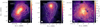 |
Fig. 1 Hydrogen column density maps (N(H2)) derived from Spitzer 8 μm extinction. The contours show the integrated intensity map of the main component of NH3 (1,1) line. The void regions in L694-2 and L1517B of very low N(H2) correspond to nearby bright point 8 μm sources. The beam size is indicated as a white filled circle in each figure. For L694-2 and L429 the contours start from 1 K km s−1 and 1.5 K km s−1, respectively, with a spacing of 0.5 K km s−1. For L1517B the contours start from 0.5 K km s−1 with a spacing of 0.3 K km s−1. |
Density profile parameters from fitting the N(H2) map derived from 8 μm extinction.
3.2 Core density profiles constrained from N(H2) maps
We assumed that the volume density profile, n(r), of the cores follows a Bonnor–Ebert-like model (Dapp & Basu 2009):
 (1)
(1)
Specifically, the radial profile has a central flat region of radius rflat, i.e. a ‘plateau’, plus a power-law decline ∝ r−2 at the outer radii up to the radius of the core, R. Since R is mostly degenerate with nc, we fixed R to 0.1 pc for the three cores. The corresponding functional form of the column density profile is derived by integrating from the centre of the core to a certain projected radius, x. We obtained the best-fit nc and rflat for the three cores, listed in Table 2. The fitted profile is shown in Fig. 2 comparing the fitted form with the measurements for the three cores separately, and in Fig. 3 it is shown for the three fitted profiles in conjunction. L429 shows the highest central density of ~106 cm−3. L1517B and L694-2 have similar central plateau sizes of ~3000 au, with L694-2 showing two times higher central density, of 8 × 105 cm−3. The enclosed core masses within 0.05 pc of L429 and L694-2 are ~8 M⊙ and ~4 M⊙, while that of L1517B is ~2 M⊙. In Fig. 3, it can be seen that the density profiles rise from L1517B to L429, so the density in L429 is higher than that in the other two cores at all radii.
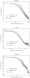 |
Fig. 2 Azimuthally averaged column density radial profiles, derived from the N(H2) map (Fig. 1). The solid red line shows the curve of the best-fit model following Eq. (1). The best-fit parameters of central density, nc, and radius of inner flat region, rflat, are indicated in each sub-plot. |
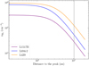 |
Fig. 3 Fitted density profiles of the three cores following the form of Dapp & Basu (2009). The vertical line marks a radius of 0.05 pc. |
3.3 Fits of the NH3 lines
To derive the physical parameters, we fitted the NH3 (1,1) and (2,2) lines simultaneously with functions in pyspecnest6 package (Sokolov et al. 2020). The method adopts Bayesian model selection to determine the spectral multiplicity, i.e. the number of velocity components, for the observed spectrum. This has been done in the past to better fit multiple components (Chen et al. 2022, Choudhury, in prep.). A nested sampling algorithm is used to explore the parameter space (pymultinest7; Buchner et al. 2014), ideal for parameter estimation in the case of multi-modal distribution. We used the cold_ammonia model in pyspeckit package8 (Ginsburg et al. 2022), which assumes that only the (1,1) and (2,2) states of para-NH3 are populated rotational levels; this is valid for cold cores (see Friesen et al. 2017). The fitting outputs best-fit parameters including system velocity, vLSR, velocity dispersion, σv, kinetic temperature, Tkin, excitation temperature, Tex, and NH3 column density, N(NH3). The ortho-to-para NH3 ratio is set to 1. We assumed uniform priors for all the parameters with boundaries set to reflect reasonable ranges for respective sources.
We note that although the total optical depth of the NH3(1,1) can be high in the central core area (τ1,1 ≳ 30), the fact that satellite lines of (1,1) are only marginally optically thick, e.g., the two hyperfine components of F = 0–1 at 23.6929 GHz have opacities of 0.074 and 0.15 times of τ1,1 and appear to be isolated components given the typical velocity dispersions associated with these cores, and that the total optical depth of the NH3(2,2) is ≲0.3, ensure that the derivation of Tkin and N(NH3) are not biased in the physical regimes in consideration. The uncertainties and degeneracies of the parameters that come with the assumptions of the model itself, i.e., a homogeneous gas layer of constant temperature along the LOS, are properly estimated by the posterior probability distributions from the nested-sampling method (Sokolov et al. 2020).
Following the logic elaborated in Sokolov et al. (2020), we set the threshold of Bayes factor, ln  , for identifying spectra that show an apparent secondary velocity component. Within our achieved rms, it turns out that for L1517B a one-component model can describe all spectra across the core, while for L694-2 and L429, there are localised sub-regions that show evidence of two velocity components. We show the ln
  maps in Appendix A. The nature of these sub-regions is discussed in Sect. 4.4. In finalising the fitted parameter maps, following Pineda et al. (2015, 2022), we trimmed the pixels with uncertainties of Tkin or Tex larger than 1 K, or uncertainties of vLSR or σv larger than two channel widths (0.2 km s−1). These criteria also ensure that N(NH3) is well constrained, with uncertainties ≲20%, as reflected from the posterior probability distributions. Small, isolated regions of less than a beam size are also removed from the final maps. Since even for L694-2 and L429, the majority of the core region is characterised by one velocity component, we present the parameter maps from the one-component model for the three cores: Tkin and N(NH3) in Fig. 4, vLSR and σv in Fig. 5.
3.4 NH3 column density and kinetic and excitation temperatures
Comparing the N(NH3) of the three cores in Fig. 4, the range of N(NH3) of core L429 and L694-2 is similar, reaching up to ~2 × 1015 cm−2 (higher than that of H-MM1; Pineda et al. 2022), while L1517B has a lower peak N(NH3), ~7 × 1014 cm−2. The morphology of the higher N(NH3) structures of L694-2 and L429 appear elongated, along the north-west to south-east, and the north to the south direction, respectively, while that of L1517B appears rounder.
The Tkin spatial distribution of all three cores are mostly uniform (Fig. 4), with a slight increase towards the outer region; this is similar to the Tkin map of H-MM1 (Pineda et al. 2022). Compared to H-MM1, which has an average central Tkin of 11 K, L429 and L694-2 show an overall lower Tkin, varying from 8-10 K. The temperature drop in the central core region is more obvious in the left plot of Fig. 6; the average temperature of L429 drops from ~9 K to below 8 K, that of L1517B from ~11 K to 10 K, while L694-2 shows a more smooth temperature structure of ~9 K.
Comparing Tkin with Tex (Fig. 7), for L1517B, Tex is systematically lower than Tkin. This indicates that the gas densities are relatively low and NH3 lines are mainly sub-thermally excited (the thermalisation density of NH3 (1,1) is ~105.5 cm−3 for a gas kinetic temperature of ~10 K; Shirley 2015). For L694-2, the Tex is closer to Tkin; L429 shows the least overall difference between Tex and Tkin. The comparison between Tkin and Tex implies a pro-gressively denser gas environment of core L1517B, L694-2, and L429, which is compatible with the density profiles determined in Sect. 3.2 (Fig. 3).
3.5 Velocity field, velocity dispersion, and velocity gradient distribution
The centroid velocities of the three cores show small variations (Fig. 5) within ~0.4 km s−1. For L694-2 and L429, the variations are within ~0.3 km s−1, and for L1517B they are within ~0.15 km s−1. The velocities of L694-2 and L1517B are more continuous across the core dominated by mostly large-scale variations, while L429 is characterised by a more complex velocity field with localised variations, showing alternating blueshifted and redshifted velocity sub-regions. For all three sources, the most redshifted and blueshifted velocities located at the outer regions of the core.
The velocity dispersions, σv, of the three cores are all below 0.2 km s−1, with L1517B showing even smaller values, of ≲0.1 km s−1. The smallest σv are located at the outer core regions (for L694-2 and L429 in the south-west, for L1517B in the south), coincident with continuous, either redshifted or blueshifted velocity field. There are some prominent, arc-like features of high σv seen towards L429 and L694-2, which are also correlated with abrupt change of vLSR or/and appearance of secondary velocity component (Appendix F). We discuss the specific gas kinematics for each core in Sect. 4.4.
Using the centroid velocity maps, we calculated the local (LOS) velocity gradient (magnitude, ℊ, and orientation, Θ) following the method elaborated in Sokolov et al. (2019), which was first presented by Goodman et al. (1993) and Caselli et al. (2002a). The chosen area for fitting the local velocity gradient and the pruning of the pixel-wise fits (based on significance of the fitted ℊ and Θ) follow that described in Sokolov et al. (2019). The sub-regions where a secondary velocity component is detected are trimmed for the local velocity gradient calculation. We first calculatde an average global velocity gradient across the core, which takes into account all the valid pixels in the centroid velocity maps. The average global velocity gradient for L694-2 is 1.65+0.03 km s−1 pc−1, for L429 it is 0.52±0.02 km s−1 pc−1, and for L1517B it is 1.77±0.03 km s−1 pc−1. These small-scale velocity gradients are in general larger than those measured from the single-dish observations towards the parental filamentary structure of the cores (see that for L1517B in Hacar & Tafalla 2011 and L694-2 in Kim et al. 2022). This reflects that the small-scale structure of the core is showing more variations of velocity field.
In Fig. 8, the obtained local velocity gradient maps of the three cores are shown. The velocity gradients have a wide range of directions, which can vary significantly over small scales, especially towards L694-2 and L429. The larger magnitudes of velocity gradient are not necessarily associated with higher N (NH3) regions. In fact, towards L429 in particular, the largest ℊ mostly lie in the outer region of the core (in the north and west). Towards L694-2, despite the unpatterned overall variations of Θ, some localised regions show converging velocity gradients, e.g. in the north-west direction, which may be driven by clumpy sub-structures that remain unresolved.
Figure 9 compares the distribution of ℊ: among the three cores, L429 exhibits a bi-modal distribution of ℊ and has an average ℊ of 3.2 ±1.4 km s−1, pc−1, similar to that measured towards L694-2 and L1517B, of 4.7±2.6 km s−1 pc−1 and 3.5±2.1 km s−1 pc−1, respectively. Considering the two times larger distance of L429 compared to the other two cores and the resultant degraded sensitivity of localised velocity variations with the same angular resolution observations, the velocity gradient of L429 is expected to be comparable or even larger than L694-2. If we assume that the measured LOS velocity gradients partially reflect the inward motions of the dense gas, then the higher average local velocity gradients of L694-2 and L429 imply, independently, that they are denser than L1517B, with a higher enclosed mass at similar scales. The more complex velocity gradient pattern of L429 also indicates it has more chaotic gas flows than the other two cores.
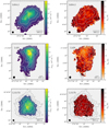 |
Fig. 4 Ammonia column density, N(NH3) and kinetic temperature, Tkin maps for the three cores, constrained from one-component fit. The beam size is indicated as a black filled circle in each image. The contours are the same as that defined in Fig. 1, showing the N(H2) levels. |
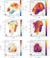 |
Fig. 5 Centroid velocity, vLSR and velocity dispersion, σv maps for the three cores, constrained from one-component fit. The beam size is indicated as a black filled circle in each image. |
 |
Fig. 6 KDE of kinetic temperature (left) and normalised kinetic temperature (right) as a function of NH3 column density. In the right figure, the kinetic temperatures of each source are transformed with |

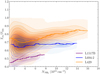 |
Fig. 7 KDE of Tex/Tkin ratio as a function of NH3 column density. The line segments correspond to mean values in NH3 column density bins, with solid lines linked together. |
3.6 Variations of NH3 abundance
In the left plot of Fig. 10, the comparisons between N (NH3) and N (H2) of the three cores are shown. L694-2 and L 1517B do not show any strong evidence of an abundance drop of NH3; L429, on the other hand, shows a continuous flattening of N (NH3) as N (H2) increases. In order to account for different background levels of H2 column density, we estimated the average N(H2) offset,  , from the outermost region (~3 beam sizes in width) of the N (NH3) map (‘zero-level’ of N(NH3), see also below) and plot the N (NH3) as a function of
  in Fig. 10, right panel. It can be seen that the slopes of L429 and L694-2 are similar in the lower
  regime of up to ~ 5 × 1022 cm−3, with L 1517B showing a higher abundance of NH3; the positive offsets of NH3 at
  are similar among the three cores of ~2 × 1014 cm−2, indicating similar NH3 column density in their embedding molecular clouds.
To describe the variation of N (NH3) as a function of N (H2), we fit a broken line model following the form detailed in Pineda et al. (2022). The functional form includes two linear slopes, a and c, which apply below and above the cut-off N (H2), x0, where the variation happens, in addition to an intercept b representing the N (NH3) at N (H2) = 0. In the case of L1517B and L694-2, the best-fit cut-off N (H2) are above the maximum N (H2) measured, indicating they are better described by a single linear relation. The fitted parameters are listed in Table 3 for the three cores; in the case of L1517B and L694-2, the best-fit cut-offs N (H2) are close to the maximum N (H2) measured, indicating they are better described by a single linear relation. Compared to the case of H-MM1, values of a are similar. The cut-off N (H2) value in L429 is ~ 8 × 1022 cm−2, which is higher than that in H-MM1. Concerning the variations of the abundance, H-MM1 shows a negative slope c at higher N(H2) which strongly indicates ammonia depletion; towards L429, we have a more flattened but still positive slope c, indicating that there is only moderate ammonia depletion happening in the centre.
Best-fit parameters of the broken line model of the three cores and H-MM1 (Pineda et al. 2022).
4 Discussion
4.1 Temperature structure
We resolved a slight decrease of gas temperature towards L429 and L1517B, varying from ~9 K to below 8 K for L429 and ~ 11 K to 10 K for L1517B. The situation resembles the case of H-MM1 (Pineda et al. 2022), while H-MM1 shows an overall higher temperature, ranging from ~ 12 K to 11 K. L694-2 shows a rather uniform temperature around 9 K, which is consistent with previous findings that suggest it is a prolate core slightly inclined to the LOS (Harvey et al. 2003). Compared to L1544 that displays a strong temperature drop down to ~6 K (Crapsi et al. 2007), these temperature variations are minor. Previous single-dish observations of NH3 towards the starless core L1517B report a constant temperature of 9.5 K (Tafalla et al. 2002, Tafalla et al. 2006), while with our improved angular resolution, we still only resolve a minor decrease of temperature, which is similar to that resolved in starless core CB17 (Spear et al. 2021) and the northern Ophiuchus D core (Ruoskanen et al. 2011). The nearly isothermal nature of these cores suggests that they are at an earlier stage of evolution (Keto & Caselli 2008), characterised by a low gas density ≲ 105 cm−3 (LOS averaged density seen by NH3), and cooling for the bulk gas is governed by molecular line emission.
The temperature drop in our sampled three cores is less significant than that in the prototypical pre-stellar core L 1544, which is likely at a more evolved stage of evolution. In L 1544, there is a drastic temperature drop seen in the inner ~2500 au down to 6 K (Crapsi et al. 2007), while L429 has a similar central density and evolutionary stage as L1544, the fact that it is located further away with an achieved angular resolution similar to 2500 au may also have hindered the significant temperature drop to be probed. One note is that Crapsi et al. (2007) used VLA-only data to estimate Tkin; in Appendix E, we present the variations of Tkin derived from VLA-only data cubes (Crapsi et al. 2007) which also only show minor drop of temperature.
4.2 Characterising the temperature structure of the cores: Radiative transfer modelling with RADMC - 3D
The central drop of gas and dust temperature in pre-stellar cores is due to shielding and irradiation of their embedded radiation field. We note that the derivation of a temperature map assuming homogeneous layer(s) is subject to the LOS averaging effect and cannot fully recover the possible underlying temperature gradient. A full radiative transfer line modelling incorporating the density, temperature, and NH3 abundance profiles tailored for the sampled cores may be more sensitive to the subtle change of the temperature structure, which is beyond the scope of this work. To understand the environment interstellar radiation field of the three cores and to gauge the gas temperature variations from NH3 lines, we conducted radiative transfer modelling with RADMC-3D (Dullemond et al. 2012), assuming that the density structure of the cores follows the 1D form derived in Sect. 3.2. We started the modelling by assuming a standard interstellar radiation field (ISRF) following the form in Hocuk et al. (2017), which consists of six modified black-body components (Zucconi et al. 2001) and a UV contribution (Draine 1978). We adjusted the scaling of the standard ISRF and arrived at different dust temperature profiles. The mass averaged temperature profile was then calculated, assuming the threshold above which the gas structures are seen by NH3 emission are 1 × 104 cm−3 for L1517B, and 2 × 104 cm−3 for L429 and L694-2. The thresholds are determined by comparing the observed Tex and Tkin relation for each source to the modelled Tex versus Tkin relation based on non-LTE calculations for NH3 column density of 6 × 1014 cm−2 (Shirley 2015).
In Fig. 11, we plot the output radial temperature profiles from RADMC-3D, together with the (projected) radial profile after mass averaging along the LOS considering the density profile constrained in Sect. 3.2. The observed physical resolution is also taken into account in the mass averaging. If we assume that dust and gas are fully coupled above a gas density of 105 cm−3 (Goldsmith 2001, indicated by the vertical solid line in Fig. 11), then the resultant temperature profile of G0 ~ 0.5 for L429 matches well to the observed gas kinetic temperature derived from NH3, showing a slight decrease from above 9 K to 8 K within the effective radius of the Tkin map derived from NH3, while for L694-2, the G0 = 0.5 ISRF produces a rather invariant ~9 K profile within the effective radius. Meanwhile, the NH3 abundance drop in the central region of L429 can further bring down the mass averaged temperature to below 8 K, since there is non-uniform sampling of gas mass along the LOS. For L1517B, the G0 = 1 ISRF produces a temperature around 11 K, although the drop is even more slight than what is observed. We therefore conclude that considering the high central density of the three cores, the gas kinetic temperatures seen by NH3 are consistent with the dust temperatures assuming the cores are bathed in standard ISRF (G0 ~ 1–2). A more significant radial temperature variation towards the three cores may be resolved with a higher sensitivity NH3 mapping, i.e. to increase the effective radius of the Tkin map.
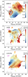 |
Fig. 8 Centroid velocity map overlaid with the velocity gradient (after subtracting the average overall velocity gradient) arrows. The subregions where a second velocity component is seen are excluded from the maps. The directions of the arrows point to the steepest velocity field change in the redshifted direction, while the arrow lengths represent the relative vector magnitudes of the gradient, with the length of 3 km s−1 pc−1 indicated in each subplot. The magenta arrow shows the average overall velocity gradient across the core; the length is artificially scaled up by a factor of ten for better representation. The contour levels indicate N(NH3) starting from 1.0 × 1014 cm−2 with an interval of 2.1 × 1014 cm−2. |
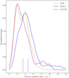 |
Fig. 9 Distribution of velocity gradient of the three cores. |
4.3 Abundance variations of NH3 in pre-stellar cores
At the lower N (H2) end (N (H2) < 8 × 1022 cm−2), the abundance of NH3 of the three cores are close, as indicated by their similar slopes between N (NH3) and N (H2) (Table 3), ~ 1.5 × 10⁻⁸. This abundance value is close to previous interferometric measurements towards other pre-stellar cores (Chitsazzadeh et al. 2014; Spear et al. 2021; Friesen et al. 2017; Pineda et al. 2022) within a factor of 2.
Adopting the new distance measurements of the three cores (Galli et al. 2019; Kim et al. 2022; Ortiz-León et al. 2018), with the high-resolution extinction map, we note that the central densities of the three cores increase from L1517B to L429; L1517B has a central density of ~3 × 105 cm−3, ~3 times lower than that towards L694-2 and L429. The fact that NH3 abundances of L694-2 and L1517B do not vary as significantly as L429 in the core centre is likely due to their overall lower density. From the relation of N (NH3) and N (H2) (Fig. 10) of L429, the cut-off N (H2) where the abundance drops is fitted to be ~ 7.5 × 1022 cm−3, and the abundance in the core centre is two times lower than at core edge (comparing a and c in Table 3). These abundance variations are similar to L1689-SMM16 (Spear et al. 2021). As we used a 1D model to describe the core density profile, we can convert the cut-off N (H2) to LOS mass averaged gas volume density 〈n (H2)〈, yielding 4.4 × 104 cm−3 for L429. Pineda et al. (2022) suggested a turnover gas density of 2.1 × 105 cm−3, beyond which the NH3 depletion is significant. With the conversion of N (H2) to 〈n (H2)〉, none of the three cores has 〈n (H2)〉 reaching 2.1 × 105 cm−3 with the present angular resolution. This explains the moderate NH3 depletion towards L429, compared to that resolved in H-MM1, as well as the rather invariant NH3 abundance towards L694-2 and L1517B, which are due to their progressively lower gas densities compared to L429. This observational trend of NH3 abundance variations is consistent with predictions of chemical models that show various degree of NH3 depletion in the central region of the cores (Sipilä et al. 2019).
Embedded in different parental molecular clouds (see Appendix A), the three cores and H-MM1 have different environmental conditions, which are also reflective in their different average temperature (dominated by the outer parts of the core), and different levels of N (H2) offset (Sect. 3.6). The fact that the NH3 abundance variation of the four cores can be consistently explained by their different central densities seems to suggest that the only relevant physical property for the depletion of NH3 is the evolutionary stage of the core.
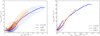 |
Fig. 10 KDE of NH3 column density as a function of H2 column density. The line segments correspond to mean values in H2 or NH3 column density bins, which are linked together. In the right panel, H2 column density is corrected by H2 offset estimated based on ‘zero-level’ of NH3 column density. |
4.4 Gas kinematics
As described in Sect. 3.5, the velocity dispersions, σv for the three cores show local variations, but are all ≲0.2 km s−1. We can estimate the thermal and non-thermal contributions using the derived Tkin while taking into account the instrumental broadening due to the channel-to-channel correlation (Pineda et al. 2010; Leroy et al. 2016; Choudhury et al. 2020). The distribution of the sonic Mach number, Ms, of the three cores is shown in Fig. 12. The cores all appear predominantly subsonic (Ms ⩽ 1); L1517B shows the least non-thermal contribution with an average Ms of 0.2; L694-2 is intermediate with an average Ms of 0.5; and L429 shows the highest Ms, on average of 0.8. The highest Ms towards L429 is consistent with its more complex velocity field and higher local velocity gradient.
Considering the stability of the cores, we can compare the scale of the inner plateau a with the Jeans length estimated from the central density nc and temperature; the scale ratio is denoted as k in Dapp & Basu (2009). For similar gas density and temperature, the larger a corresponds to a reduced pressure gradient, and the core is more likely collapsing with prevailing self-gravity. With central temperatures of 10 K for L1517B and 8 K for L694-2 and L429, we arrive at k values of 0.8 of L1517B and 1.3 for both L694-2 and L429. Since the central temperature is estimated from the Tkin maps, which involve LOS averaging, which for a centrally dropping temperature profile is higher than the real temperature, these k values are likely upper limits. Nonetheless, this suggests that L429 and L694-2 are in a more evolved evolutionary phase than L1517B.
The embedding filament of L1517B shows signatures of velocity oscillation (Hacar & Tafalla 2011) and the core itself seems to reside at the position of converging velocities. The parental filamentary structure exhibits a similar velocity field among tracers sensitive to different density regimes (Hacar & Tafalla 2011), appearing to be a velocity coherent structure up to 0.5 pc with subsonic motions. Indeed, the resolved continuous variation of the velocity field inside L1517B, from the north-east to south-west (Fig. 5), roughly follows the large-scale filament structure where the velocity gradients may vary in direction due to the flow converging. The velocity turning from the large-scale filament may also originate partially from the filament rotation (e.g. Álvarez-Gutiérrez et al. 2021). This may reflect that the physical status of L1517B is close to quasi-static contraction, with the small-scale velocity gradient (~ 2 km s−1 pc−1; Sect. 3.5) slightly larger than that along the embedding filament (~ 1.4 km s−1 pc−1).
For L694-2 and L429, the sharp gradients and multiple velocity components (in sub-regions, Appendix F) found at the edge of the cores might be the signature of the ongoing accretion of material from cloud to core (e.g. Choudhury et al. 2020, Choudhury et al. 2021; Chen et al. 2022), which remains to be further studied with larger scale maps and better sensitivity. Cloud-to-core accretion has already been deduced with observations of HCO+ (e.g. Redaelli et al. 2022) and CS (e.g. Mardones et al. 1997). How these cloud-core feeding flows link to the even smaller scale asymmetric accretion streamers surrounding the young stellar objects (core-to-disc flows; e.g. Pineda et al. 2020, Pineda et al. 2023) carry essential clues of how protostars gain masses under the complex interplay of physical mechanisms over different spatial scales.
5 Conclusions
We present NH3(1,1) and (2,2) data combined from VLA and GBT observations, for one starless core, L1517B, and two pre-stellar cores, L694-2 and L429. We derive the parameter maps from fitting the NH3 lines and obtain the gas kinetic and excitation temperature, NH3 column density, centroid velocity, and velocity dispersion maps. We use Spitzer 8 µm to derive high angular resolution hydrogen column density maps for the three cores. Our main findings are as follows:
A minor temperature drop is resolved towards L429 and L1517B, showing 9 K at core edge to below 8 K in centre, and 11 K to 10 K, respectively. L694-2 shows a uniform temperature structure of ~ 9 K. These resolved gas radial temperature profiles are roughly consistent with each core’s LOS mass averaged dust temperature profiles with a standard ISRF, considering their different gas density profiles and our effective mapping scales;
The Bonnor–Ebert-like gas density profiles are constrained from the high-resolution extinction map (5″). The central density of L429 and L694-2 appears the largest, 0.8−1 × 106 cm−3, while L1517B has a central density of 3.2 × 105 cm−3;
The line widths are predominantly subsonic with a progressive overall increase from L1517B, L694-2, and L429, consistent with the increasing magnitude of the local velocity gradient. The velocity fields of L1517B and L694-2 show relatively large-scale variations, likely reflecting a mixture of contracting motions and acoustic oscillation. L429 exhibits more localised velocity changes, possibly reflecting an advanced collapse phase that involves more complex gas motions;
The NH3 abundance becomes ~2 times lower in the central region of L429, which happens around a hydrogen column density of 7.5 × 1022 cm−2. The corresponding (LOS mass-averaged) H2 volume density is 4.4 × 104 cm−3. This is below the cut-off density of ~2 × 105 cm−3· where a stronger abundance drop is seen towards H-MM1 (Pineda et al. 2022). L694-2 and L1517 show a rather invariant NH3 abundance. Overall, the three cores plus H-MM1 compose a consistent trend of NH3 depletion with increasing gas density in the central region of pre-stellar cores.
Our results demonstrate the importance of carrying out high-angular resolution observations of NH3 lines to understand the chemistry of NH3 in starless and pre-stellar cores as well as to maximize the diagnostic power of these lines in probing the thermal structures. A matched angular resolution hydrogen column density map is essential to uncover the abundance variations of NH3 which only appear in the very heart (≲4000 au) of these cold and dense cores. We expect future observations from, especially, the Next-Generation Very Large Array (ngVLA), to unveil the detailed, locally varying thermal and kinematic structures of these pristine star-forming sites, and advance our knowledge of the physics regulating Solar-type star formation.
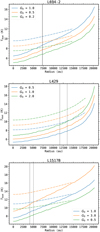 |
Fig. 11 Radial temperature profiles (solid lines) calculated by RADMC-3D assuming different ISRF intensity, and the corresponding LOS mass averaged temperature profiles (dash-dotted lines). The vertical solid line in grey indicates the position within which gas density is above 105 cm−3 for each core. The vertical dotted line mark the effective radius of the obtained Tkin map from fitting the NH3 (1,1) and (2,2) lines. |
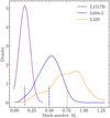 |
Fig. 12 KDE of Mach number of the three cores. The mean values are indicated with vertical line segments of respective colours. |
Acknowledgements
The authors acknowledge the financial support of the Max Planck Society. H.B.L. is supported by the National Science and Technology Council (NSTC) of Taiwan (Grant No. 111-2112-M-110-022-MY3).
Appendix A Target sources
L694-2 is a relatively isolated pre-stellar core (Lee & Myers 2011, Spezzano et al. 2016). Based on Gaia Data Release 2 astrometric data, the new distance of L694-2 is updated to 203 pc (Kim et al. 2022). Observations of N2H+ (1-0), DCO+ (2-1) and HCO+ (3-2), (4-3) lines all show blue-skewed profiles, which suggest infall motions from the extended region down to the inner core area (Williams et al. 2006, Keown et al. 2016, Kim et al. 2022). Compared to the proto-typical late-stage pre-stellar core L1544 (Keto & Caselli 2010, Caselli et al. 2019, Caselli et al. 2022), its density gradient is smaller (Williams et al. 2006), with larger infall velocities associated with outer layers (Keown et al. 2016). These indicate L694-2 is a less evolved pre-stellar core than L1544. In addition, the core appears to be elongated and its density profile analysis based on near-infrared extinction suggests that it is likely a prolate structure with the major axis slightly inclined with respect to the LOS (Harvey et al. 2003). L694-2 has an embedding cloud that appears to be filamentary, and evidence of gas flows originating from the parental cloud that feed the core has been found (Kim et al. 2022).
L429 is a late-stage pre-stellar core that holds high deuterium fraction among samples of starless cores (Crapsi et al. 2005, Bacmann et al. 2003, Caselli et al. 2008). The core is likely associated with the Aquila Rift, located at a distance of 436 pc (Ortiz-León et al. 2018). It appears to be a dark absorption feature even at 70 µm, reflecting that very dense gas is residing within the core, which may be already collapsing if there is not strong magnetic field support (Stutz et al. 2009). This is compatible with the tentative infall signatures shown in the CS (3-2) line (as L429-1 in the survey of Lee et al. 2004) and HCN (1-0) line (Sohn et al. 2007). However, red-skewed line profiles of CS lines are also detected towards the core (Lee & Myers 2011); according to the evolutionary sequence drawn by Lee & Myers (2011), L429 is marked as an intermediate evolutionary stage, between L1517B and L694-2, showing expanding motions when a static core is being perturbed.
L1517B is a starless core located in the molecular Taurus-Auriga cloud (Elias 1978, Galli et al. 2019), which is close to a state of thermal equilibrium (Crapsi et al. 2005, Tafalla et al. 2004, Kirk et al. 2006). The chemical modelling of Maret et al. (2013) suggests the core is at an evolved stage that may quickly collapse to form a protostar. Single-dish observations towards L1517B reveal systematically red-skewed line profiles (Tafalla et al. 2004, Sohn et al. 2007, Fu et al. 2011). Analytical works of Fu et al. (2011) suggest that L1517B is a typical core that shows coexistence of envelope expansion (or oscillating motions, e.g., Lou & Gao 2011) and core collapse, which produce the observed spectra. The deuteration fraction derived from N2D+ and H2D+ of L1517B is much lower than that of L429 and L694-2 (Crapsi et al. 2005, Caselli et al. 2008, Koumpia et al. 2020), indicating L1517B is at an earlier evolutionary stage than L429 and L694-2 (see also Schnee et al. 2013).
Appendix B Derivation of the combined 850 µm map
We retrieved the raw data of SCUBA2 850µm of L429 and L694-2 from the Canadian Astronomy Data Center (CADC9) archive. SMURF software (Chapin et al. 2013) implemented in the Starlink package10 is adopted for the data reduction. We used the Makemap command with the configuration file11 suited for bright extended sources; compared to the parameters used for the generic pipeline products, a less aggressive spatial filtering of the raw map is conducted in the initial data cleaning to better preserve the extended structures.
We extrapolated a 850 µm flux map from SED of Herschel SPIRE data and used this map as a model image to deconvolve the Planck image with the Lucy-Richardson algorithm (Lucy 1974). The obtained deconvolved Planck image has an angular resolution close to the SPIRE 500 µm image and preserves the flux level of the Planck image. The latter property is essential as the SCUBA2 maps suffer from different level of missing fluxes, which can be source sensitive, depending on the observing weather condition and data reduction parameters. The deconvolved image that contains the extended emission structures was then combined with the SCUBA2 850 µm image in the Fourier domain using J - comb algorithm (Jiao et al. 2022). The method has proved to be superior to conventional linear image combination methods implemented in, e.g., immerge in miriad and feather in CASA, by largely suppressing imaging defects inherent to the ground-based bolometric observations as well as conserving the high-resolution Gaussian beam pattern (Jiao et al. 2022). The obtained 14″ combined 850 µm map of L694-2 and L429 is shown in Fig. B.1. Applying the Td map from SED of Herschel SPIRE data, we calculate the N(H2) map shown in Fig. B.2.
 |
Fig. B.1 850 μm emission maps combining SCUBA2 850 μm and deconvolved Planck images of L694-2 and L429. |
 |
Fig. B.2 14″ hydrogen column density map derived from combined 850 μm map shown in Fig. B.1 and Td map from SED of Herschel data. |
Appendix C Comparison between adopted methods for the combination of VLA and GBT data
We adopted both the joint deconvolution method using Miriad and the model-assisted clean method using CASA, for the combination of VLA and GBT data. The last step of both methods involves linearly adding the single-dish data with the previous, intermediate combined product in the Fourier domain with feather and immerge task implemented in each software. In particular, the mathematical form used in the immerge task ensures the total flux (within the primary beam) of the final combined image preserves that of the single-dish data (see e.g. Jiao et al. (2022)).
A thorough benchmark between the two methods, dependent on the input parameters (e.g. the weighting of the single-dish data in the first method) and the characteristics of the observational data (e.g. sparse or decent uv sampling of the inter-ferometric data, overlapping scales between the single-dish and interferometric data, etc.), is beyond the scope of this paper. In what follows, we simply compare the fitted NH3 column density (N(NH3)) using the combined image products from the two methods, shown in Fig. C.1. We found there is no significant discrepancy or systematic bias of the two set of (N(NH3)) values, which means that the different combination approaches should not affect the analysis and comparison of our results with respect to Pineda et al. (2022).
 |
Fig. C.1 2D histogram of comparison between fitted N(NH3) of different combined data products: one based on joint-deconvolution (JD) and immerge using Miriad and the other model-assisted (MA) multi-scale clean plus feather using CASA. The diagonal dashed and solid lines indicate a factor of 1.2, 1, and 0.8 differences. |
Appendix D Derivation and uncertainty of N(H2)
We used the SMF method in Butler & Tan (2009) for background emission level estimates. After testing a set of different sized filters, we settled with a filter size of 90″, which minimises the visual defect of interpolation while still preserving the median-to-large-scale background emission pattern. The difference of the average background emission level for a filter size ranging between 60-270″ is within 10%.
Practically, the assumption of constant foreground emission level can cause underestimation of the column densities, particularly in the outer parts of the core. By inspecting the 8µm map and the contours of N(H2) map from Herschel it is obvious that some bright 8µm emission is associated with the foreground of the source. The small-scale median filter method effectively removes all contribution from compact bright sources for interpolation at the core area, ignoring the fact that there may be a bunch of stars that compose the background of the cores. The uncertainties associated with background and foreground emission level estimates are hard, if not impossible, to assess. We resorted to matching the τ profiles from the extinction method and from that the SED by a constant scaling factor. This is essentially based on the assumption that the morphological features of the N(H2) map derived by the extinction method preserve the real profiles of the core structure without spatially varying degrees of deficit. This is largely based on what we find empirically; the constant scaling up can match the column density cuts along the core for the inner part and outer part simultaneously. The comparison between the profiles of original τ8 µm and that predicted from τ850 µm are shown in Fig. D.1, together with the scaled-up τ8 µm. Comparing the ratios between the scaled-up τ8 µm and that predicted from τ850 µm, the consistency of ~ 1 can be achieved for most of our interested core area.
As a simple sanity check, we derived the foreground image of 8 µm using the scaled-up 2″ column density map and assumed the background image estimated from SMF is relatively robust. The level of the derived foreground image, compared to the constant Ifg we assumed, is a factor of 1.0-1.6 times higher for the pixels in the core area. This is a reasonable difference in terms of possible underestimates of the foreground emission level.
In fact, the deficit of the derived N(H2) (after smoothing) compared to that derived from SED of Herschel data can have different origins. For the outer parts of the core, it is mainly the intrinsic problem of extinction method being not sensitive to lower column density regime due to the way foreground and background emission level are estimated; for the central part of the core, there is possible variation of the dust opacities due to grain growth at high density. Specifically, we used the thin ice mantle without coagulation according to the models of Ossenkopf & Henning (1994), while the ratio of  can be lowered to 50% with dust coagulation and thicker ice layers Ossenkopf & Henning 1994. This change of dust opacities can reconcile the less than 1.5 times underestimated N(H2) from 8µm extinction, but it is expected to be most significant in the central ~ 1000 au region (e.g. Chacón-Tanarro et al. 2019).
The scaling factors of L1517B and L694-2 are 1.5 and 1.8, and for L429 it is ~2.5. This suggests that L429 is missing the most gas column densities from the extinction method. Indeed, the ambient cloud structure of L429 shows the highest level of gas column densities, reaching 5 × 1022 cm−3 as seen from the Herschel map.
The uncertainty of N(H2), which comes from the dust grain scattering (main aggregates) and possible emission at 8 µm (Lefèvre et al. 2016, Steinacker et al. 2005), is negligible ( ~0.1 MJy sr−1) compared to the uncertainty of the background and foreground emission level estimates (Pineda et al. 2022) for a source with extended sky brightness of several times 1 MJy sr−1 at 8 µm. We note that this is the case for all the three cores in our sample.
 |
Fig. D.1 Comparison between profiles (along Declination) of opacity maps, extracted from original τ8 µm map, and that predicted from τ850 µm (denoted as |


Appendix E Tkin derived from VLA-only data cubes
In Crapsi et al. (2007), the temperature drop towards L1544 is revealed by the temperature map derived from VLA-only data cubes of the NH3 (1,1) and (2,2) lines. This means that the extended structure is missing, which presumably affects the emission of the low-lying energy levels most, since these can be excited at lower density layers. The extent and degree of the missing extended structure is hard, if not impossible, to predict. We tested fitting the NH3 models with the VLA-only NH3 (1,1) and (2,2) lines and compare the distribution of Tkin versus N(NH3) (as in Fig. 6, left panel) in Fig. E.1. Compared to results derived from combined data cubes, a large difference is seen towards L1517B, which shows an overall lower temperature of ≲8 K, close to that towards L429 and L694-2. With VLA-only data, there is still not a significant temperature drop of the three cores as that revealed towards L1544. The temperature variations of L429 in the VLA-only data are even more flattened than that in the combined data. This shows that the slight temperature drops seen in the combined data towards L429 and L1517B are mainly associated with (the LOS weighting of) outer gas layers of the core, where the region under influence of radiation field is better preserved.
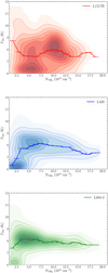 |
Fig. E.1 Kinetic temperature as a function of NH3 column density for the three cores. Both quantities are derived from VLA data cube without combining with GBT data (as compared to right panel of Fig. 6). The line segments correspond to mean values in H2 column density bins, which are linked together. |
Appendix F Sub-regions with secondary velocity component
As stated in Sect. 3.3, for sub-regions of L694-2 and L429, there is evidence of a secondary velocity component. We present the two-component velocity and line-width maps in Figs. F.1 and F.4 and the example spectra across the sub-regions that have two or one velocity component in Figs. F.2, F.3, F.5, and F.5. When generating the parameter maps, for the vast region where a one-component fit is statistically preferred, the fitted values from this fit are assigned to corresponding pixels. In Figs. F.1–F.4, sub-regions showing two velocity components are marked by closed contours. These sub-regions are selected based on the  threshold and trimmed according to fitted errors. Compared to trimming the one-component fit in Sect. 3.3, we used less strict criteria: uncertainties of Tkin or Tex larger than 2 K, υLSR or σ larger than four channel widths (0.4 km s−1).
Examining Fig. F.4 and Fig. F.1, it is clear that the sub-regions showing a secondary velocity component are where there are abrupt changes of the one-component velocity map. Comparing the two-component velocities with the one-component velocity of the main regions across the core, mostly, the velocity component that has a larger line width seems to show a better consistency with main regions. The redshifted, smaller line-width sub-regions connect to the outermost region of the core, which is clearer in the case of L429.
 |
Fig. F.1 Velocity and line-width maps of L694-2 combining sub-regions where a secondary velocity component exist and the rest regions showing only one velocity component. The two-component sub-regions are enclosed by contours, defined by |

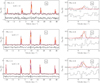 |
Fig. F.2 Example of two-component spectra towards S1, S2 and S3 regions of L694-2 as in Fig. F.1 (cyan pluses), of the NH3 (1,1) and (2,2) lines. Red dashed lines show the overall two-component fit; orange and magenta lines shows the two components separately. The offset spectra show the residual of observed spectra minus the two-component model spectra. |
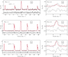 |
Fig. F.3 Same as Fig. F.2, but of the spectra in the inner region of S1, S2 and S3 (blue crosses in Fig. F.1) that only show one velocity component. |
References
- Aikawa, Y., Herbst, E., Roberts, H., & Caselli, P. 2005, ApJ, 620, 330 [NASA ADS] [CrossRef] [Google Scholar]
- Álvarez-Gutiérrez, R. H., Stutz, A. M., Law, C. Y., et al. 2021, ApJ, 908, 86 [CrossRef] [Google Scholar]
- Bacmann, A., Lefloch, B., Ceccarelli, C., et al. 2003, ApJ, 585, L55 [NASA ADS] [CrossRef] [Google Scholar]
- Bergin, E. A., & Tafalla, M. 2007, ARA&A, 45, 339 [Google Scholar]
- Bergin, E. A., Maret, S., van der Tak, F. F. S., et al. 2006, ApJ, 645, 369 [NASA ADS] [CrossRef] [Google Scholar]
- Buchner, J., Georgakakis, A., Nandra, K., et al. 2014, A&A, 564, A125 [NASA ADS] [CrossRef] [EDP Sciences] [Google Scholar]
- Butler, M. J., & Tan, J. C. 2009, ApJ, 696, 484 [NASA ADS] [CrossRef] [Google Scholar]
- Caselli, P., & Ceccarelli, C. 2012, A&ARv, 20, 56 [Google Scholar]
- Caselli, P., Walmsley, C. M., Tafalla, M., Dore, L., & Myers, P. C. 1999, ApJ, 523, L165 [Google Scholar]
- Caselli, P., Walmsley, C. M., Zucconi, A., et al. 2002a, ApJ, 565, 331 [NASA ADS] [CrossRef] [Google Scholar]
- Caselli, P., Walmsley, C. M., Zucconi, A., et al. 2002b, ApJ, 565, 344 [Google Scholar]
- Caselli, P., Vastel, C., Ceccarelli, C., et al. 2008, A&A, 492, 703 [NASA ADS] [CrossRef] [EDP Sciences] [Google Scholar]
- Caselli, P., Pineda, J. E., Zhao, B., et al. 2019, ApJ, 874, 89 [NASA ADS] [CrossRef] [Google Scholar]
- Caselli, P., Pineda, J. E., Sipilä, O., et al. 2022, ApJ, 929, 13 [NASA ADS] [CrossRef] [Google Scholar]
- Chacón-Tanarro, A., Caselli, P., Bizzocchi, L., et al. 2017, A&A, 606, A142 [NASA ADS] [CrossRef] [EDP Sciences] [Google Scholar]
- Chacón-Tanarro, A., Pineda, J. E., Caselli, P., et al. 2019, A&A, 623, A118 [NASA ADS] [CrossRef] [EDP Sciences] [Google Scholar]
- Chapin, E. L., Berry, D. S., Gibb, A. G., et al. 2013, MNRAS, 430, 2545 [Google Scholar]
- Chen, M. C.-Y., Di Francesco, J., Pineda, J. E., Offner, S. S. R., & Friesen, R. K. 2022, ApJ, 935, 57 [NASA ADS] [CrossRef] [Google Scholar]
- Chitsazzadeh, S., Di Francesco, J., Schnee, S., et al. 2014, ApJ, 790, 129 [NASA ADS] [CrossRef] [Google Scholar]
- Choudhury, S., Pineda, J. E., Caselli, P., et al. 2020, A&A, 640, A6 [Google Scholar]
- Choudhury, S., Pineda, J. E., Caselli, P., et al. 2021, A&A, 648, A114 [NASA ADS] [CrossRef] [EDP Sciences] [Google Scholar]
- Crapsi, A., Caselli, P., Walmsley, C. M., et al. 2005, ApJ, 619, 379 [Google Scholar]
- Crapsi, A., Caselli, P., Walmsley, M. C., & Tafalla, M. 2007, A&A, 470, 221 [NASA ADS] [CrossRef] [EDP Sciences] [Google Scholar]
- Currie, M. J., Berry, D. S., Jenness, T., et al. 2014, in ASP Conf. Ser., 485, Astronomical Data Analysis Software and Systems XXIII, eds. N. Manset, & P. Forshay, 391 [Google Scholar]
- Dapp, W. B., & Basu, S. 2009, MNRAS, 395, 1092 [NASA ADS] [CrossRef] [Google Scholar]
- Draine, B. T. 1978, ApJS, 36, 595 [Google Scholar]
- Dullemond, C. P., Juhasz, A., Pohl, A., et al. 2012, Astrophysics Source Code Library [record ascl:1202.015] [Google Scholar]
- Elias, J. H. 1978, ApJ, 224, 857 [NASA ADS] [CrossRef] [Google Scholar]
- Evans, Neal J., I., Rawlings, J. M. C., Shirley, Y. L., & Mundy, L. G. 2001, ApJ, 557, 193 [NASA ADS] [CrossRef] [Google Scholar]
- Flower, D. R., Pineau Des Forêts, G., & Walmsley, C. M. 2006, A&A, 456, 215 [NASA ADS] [CrossRef] [EDP Sciences] [Google Scholar]
- Friesen, R. K., Di Francesco, J., Shirley, Y. L., & Myers, P. C. 2009, ApJ, 697, 1457 [Google Scholar]
- Friesen, R. K., Pineda, J. E., Rosolowsky, E., et al. 2017, ApJ, 843, 63 [NASA ADS] [CrossRef] [Google Scholar]
- Fu, T.-M., Gao, Y., & Lou, Y.-Q. 2011, ApJ, 741, 113 [NASA ADS] [CrossRef] [Google Scholar]
- Galli, D., Walmsley, M., & Gonçalves, J. 2002, A&A, 394, 275 [NASA ADS] [CrossRef] [EDP Sciences] [Google Scholar]
- Galli, P. A. B., Loinard, L., Bouy, H., et al. 2019, A&A, 630, A137 [NASA ADS] [CrossRef] [EDP Sciences] [Google Scholar]
- Ginsburg, A., Sokolov, V., de Val-Borro, M., et al. 2022, AJ, 163, 291 [NASA ADS] [CrossRef] [Google Scholar]
- Goldsmith, P. F. 2001, ApJ, 557, 736 [Google Scholar]
- Goodman, A. A., Benson, P. J., Fuller, G. A., & Myers, P. C. 1993, ApJ, 406, 528 [Google Scholar]
- Griffin, M. J., Abergel, A., Abreu, A., et al. 2010, A&A, 518, A3 [Google Scholar]
- Hacar, A., & Tafalla, M. 2011, A&A, 533, A34 [NASA ADS] [CrossRef] [EDP Sciences] [Google Scholar]
- Harju, J., Daniel, F., Sipilä, O., et al. 2017, A&A, 600, A61 [NASA ADS] [CrossRef] [EDP Sciences] [Google Scholar]
- Harju, J., Pineda, J. E., Vasyunin, A. I., et al. 2020, ApJ, 895, 101 [NASA ADS] [CrossRef] [Google Scholar]
- Harvey, D. W. A., Wilner, D. J., Lada, C. J., Myers, P. C., & Alves, J. F. 2003, ApJ, 598, 1112 [NASA ADS] [CrossRef] [Google Scholar]
- Ho, P. T. P., & Townes, C. H. 1983, ARA&A, 21, 239 [NASA ADS] [CrossRef] [Google Scholar]
- Hocuk, S., Szucs, L., Caselli, P., et al. 2017, A&A, 604, A58 [NASA ADS] [CrossRef] [EDP Sciences] [Google Scholar]
- Hotzel, S., Harju, J., Lemke, D., Mattila, K., & Walmsley, C. M. 2001, A&A, 372, 302 [NASA ADS] [CrossRef] [EDP Sciences] [Google Scholar]
- Jiao, S., Lin, Y., Shui, X., et al. 2022, Sci. China Phys. Mech. Astron., 65, 299511 [NASA ADS] [CrossRef] [Google Scholar]
- Juvela, M., Harju, J., Ysard, N., & Lunttila, T. 2012, A&A, 538, A133 [NASA ADS] [CrossRef] [EDP Sciences] [Google Scholar]
- Keown, J., Schnee, S., Bourke, T. L., et al. 2016, ApJ, 833, 97 [Google Scholar]
- Keto, E., & Caselli, P. 2008, ApJ, 683, 238 [Google Scholar]
- Keto, E., & Caselli, P. 2010, MNRAS, 402, 1625 [Google Scholar]
- Keto, E., & Field, G. 2005, ApJ, 635, 1151 [NASA ADS] [CrossRef] [Google Scholar]
- Keto, E., Caselli, P., & Rawlings, J. 2015, MNRAS, 446, 3731 [NASA ADS] [CrossRef] [Google Scholar]
- Kim, S., Lee, C. W., Tafalla, M., et al. 2022, ApJ, 940, 112 [NASA ADS] [CrossRef] [Google Scholar]
- Kirk, J. M., Ward-Thompson, D., & Crutcher, R. M. 2006, MNRAS, 369, 1445 [CrossRef] [Google Scholar]
- Koumpia, E., Evans, L., Di Francesco, J., van der Tak, F. F. S., & Oudmaijer, R. D. 2020, A&A, 643, A61 [NASA ADS] [CrossRef] [EDP Sciences] [Google Scholar]
- Lee, C. W., & Myers, P. C. 2011, ApJ, 734, 60 [NASA ADS] [CrossRef] [Google Scholar]
- Lee, C. W., Myers, P. C., & Plume, R. 2004, ApJS, 153, 523 [NASA ADS] [CrossRef] [Google Scholar]
- Lefèvre, C., Pagani, L., Min, M., Poteet, C., & Whittet, D. 2016, A&A, 585, A4 [NASA ADS] [CrossRef] [EDP Sciences] [Google Scholar]
- Leroy, A. K., Hughes, A., Schruba, A., et al. 2016, ApJ, 831, 16 [Google Scholar]
- Lin, Y., Liu, H. B., Li, D., et al. 2016, ApJ, 828, 32 [NASA ADS] [CrossRef] [Google Scholar]
- Lin, Y., Wyrowski, F., Liu, H. B., et al. 2022, A&A, 658, A128 [NASA ADS] [CrossRef] [EDP Sciences] [Google Scholar]
- Liu, H. B., Galván-Madrid, R., Jiménez-Serra, I., et al. 2015, ApJ, 804, 37 [Google Scholar]
- Lou, Y.-Q., & Gao, Y. 2011, MNRAS, 412, 1755 [CrossRef] [Google Scholar]
- Lucy, L. B. 1974, AJ, 79, 745 [Google Scholar]
- Mardones, D., Myers, P. C., Tafalla, M., et al. 1997, ApJ, 489, 719 [Google Scholar]
- Maret, S., Bergin, E. A., & Tafalla, M. 2013, A&A, 559, A53 [NASA ADS] [CrossRef] [EDP Sciences] [Google Scholar]
- Monsch, K., Pineda, J. E., Liu, H. B., et al. 2018, ApJ, 861, 77 [NASA ADS] [CrossRef] [Google Scholar]
- Myers, P. C., & Benson, P. J. 1983, ApJ, 266, 309 [CrossRef] [Google Scholar]
- Ortiz-León, G. N., Loinard, L., Dzib, S. A., et al. 2018, ApJ, 869, L33 [Google Scholar]
- Ossenkopf, V., & Henning, T. 1994, A&A, 291, 943 [NASA ADS] [Google Scholar]
- Pagani, L., Bacmann, A., Cabrit, S., & Vastel, C. 2007, A&A, 467, 179 [NASA ADS] [CrossRef] [EDP Sciences] [Google Scholar]
- Pineda, J. E., Goodman, A. A., Arce, H. G., et al. 2010, ApJ, 712, L116 [Google Scholar]
- Pineda, J. E., Goodman, A. A., Arce, H. G., et al. 2011, ApJ, 739, L2 [NASA ADS] [CrossRef] [Google Scholar]
- Pineda, J. E., Offner, S. S. R., Parker, R. J., et al. 2015, Nature, 518, 213 [NASA ADS] [CrossRef] [Google Scholar]
- Pineda, J. E., Segura-Cox, D., Caselli, P., et al. 2020, Nat. Astron., 4, 1158 [NASA ADS] [CrossRef] [Google Scholar]
- Pineda, J. E., Harju, J., Caselli, P., et al. 2022, AJ, 163, 294 [NASA ADS] [CrossRef] [Google Scholar]
- Pineda, J. E., Arzoumanian, D., Andre, P., et al. 2023, ASP Conf. Ser., 534, 233 [NASA ADS] [Google Scholar]
- Redaelli, E., Chacón-Tanarro, A., Caselli, P., et al. 2022, ApJ, 941, 168 [NASA ADS] [CrossRef] [Google Scholar]
- Rodgers, S. D., & Charnley, S. B. 2001, ApJ, 553, 613 [CrossRef] [Google Scholar]
- Roueff, E., Lis, D. C., van der Tak, F. F. S., Gerin, M., & Goldsmith, P. F. 2005, A&A, 438, 585 [NASA ADS] [CrossRef] [EDP Sciences] [Google Scholar]
- Ruoskanen, J., Harju, J., Juvela, M., et al. 2011, A&A, 534, A122 [NASA ADS] [CrossRef] [EDP Sciences] [Google Scholar]
- Sault, R. J., Teuben, P. J., & Wright, M. C. H. 1995, in ASP Conf. Ser., 77, Astronomical Data Analysis Software and Systems IV, eds. R. A. Shaw, H. E. Payne, & J. J. E. Hayes, 433 [NASA ADS] [Google Scholar]
- Schnee, S., Brunetti, N., Di Francesco, J., et al. 2013, ApJ, 777, 121 [NASA ADS] [CrossRef] [Google Scholar]
- Shirley, Y. L. 2015, PASP, 127, 299 [Google Scholar]
- Sipilä, O., Harju, J., Caselli, P., & Schlemmer, S. 2015, A&A, 581, A122 [NASA ADS] [CrossRef] [EDP Sciences] [Google Scholar]
- Sipilä, O., Caselli, P., Redaelli, E., Juvela, M., & Bizzocchi, L. 2019, MNRAS, 487, 1269 [Google Scholar]
- Sohn, J., Lee, C. W., Park, Y.-S., et al. 2007, ApJ, 664, 928 [NASA ADS] [CrossRef] [Google Scholar]
- Sokolov, V., Wang, K., Pineda, J. E., et al. 2019, ApJ, 872, 30 [NASA ADS] [CrossRef] [Google Scholar]
- Sokolov, V., Pineda, J. E., Buchner, J., & Caselli, P. 2020, ApJ, 892, L32 [NASA ADS] [CrossRef] [Google Scholar]
- Spear, S., Maureira, M. J., Arce, H. G., et al. 2021, ApJ, 923, 231 [NASA ADS] [CrossRef] [Google Scholar]
- Spezzano, S., Bizzocchi, L., Caselli, P., Harju, J., & Brünken, S. 2016, A&A, 592, L11 [NASA ADS] [CrossRef] [EDP Sciences] [Google Scholar]
- Steinacker, J., Bacmann, A., Henning, T., Klessen, R., & Stickel, M. 2005, A&A, 434, 167 [NASA ADS] [CrossRef] [EDP Sciences] [Google Scholar]
- Stutz, A. M., Bourke, T. L., Rieke, G. H., et al. 2009, ApJ, 690, L35 [NASA ADS] [CrossRef] [Google Scholar]
- Tafalla, M., Myers, P. C., Caselli, P., Walmsley, C. M., & Comito, C. 2002, ApJ, 569, 815 [Google Scholar]
- Tafalla, M., Myers, P. C., Caselli, P., & Walmsley, C. M. 2004, A&A, 416, 191 [NASA ADS] [CrossRef] [EDP Sciences] [Google Scholar]
- Tafalla, M., Santiago-García, J., Myers, P. C., et al. 2006, A&A, 455, 577 [NASA ADS] [CrossRef] [EDP Sciences] [Google Scholar]
- Walmsley, C. M., & Ungerechts, H. 1983, A&A, 122, 164 [Google Scholar]
- Williams, J. P., Lee, C. W., & Myers, P. C. 2006, ApJ, 636, 952 [NASA ADS] [CrossRef] [Google Scholar]
- Zucconi, A., Walmsley, C. M., & Galli, D. 2001, A&A, 376, 650 [NASA ADS] [CrossRef] [EDP Sciences] [Google Scholar]
The James Clerk Maxwell Telescope is operated by the East Asian Observatory on behalf of The National Astronomical Observatory of Japan; Academia Sinica Institute of Astronomy and Astrophysics; the Korea Astronomy and Space Science Institute; the National Astronomical Research Institute of Thailand; Center for Astronomical Mega-Science (as well as the National Key R&D Program of China with No. 2017YFA0402700). Additional funding support is provided by the Science and Technology Facilities Council of the United Kingdom and participating universities and organisations in the United Kingdom and Canada.
The Starlink software (Currie et al. 2014) is currently supported by the East Asian Observatory.
All Tables
Density profile parameters from fitting the N(H2) map derived from 8 μm extinction.
Best-fit parameters of the broken line model of the three cores and H-MM1 (Pineda et al. 2022).
All Figures
|
Fig. 1 Hydrogen column density maps (N(H2)) derived from Spitzer 8 μm extinction. The contours show the integrated intensity map of the main component of NH3 (1,1) line. The void regions in L694-2 and L1517B of very low N(H2) correspond to nearby bright point 8 μm sources. The beam size is indicated as a white filled circle in each figure. For L694-2 and L429 the contours start from 1 K km s−1 and 1.5 K km s−1, respectively, with a spacing of 0.5 K km s−1. For L1517B the contours start from 0.5 K km s−1 with a spacing of 0.3 K km s−1. |
| In the text | |
|
Fig. 2 Azimuthally averaged column density radial profiles, derived from the N(H2) map (Fig. 1). The solid red line shows the curve of the best-fit model following Eq. (1). The best-fit parameters of central density, nc, and radius of inner flat region, rflat, are indicated in each sub-plot. |
| In the text | |
|
Fig. 3 Fitted density profiles of the three cores following the form of Dapp & Basu (2009). The vertical line marks a radius of 0.05 pc. |
| In the text | |
|
Fig. 4 Ammonia column density, N(NH3) and kinetic temperature, Tkin maps for the three cores, constrained from one-component fit. The beam size is indicated as a black filled circle in each image. The contours are the same as that defined in Fig. 1, showing the N(H2) levels. |
| In the text | |
|
Fig. 5 Centroid velocity, vLSR and velocity dispersion, σv maps for the three cores, constrained from one-component fit. The beam size is indicated as a black filled circle in each image. |
| In the text | |
|
Fig. 6 KDE of kinetic temperature (left) and normalised kinetic temperature (right) as a function of NH3 column density. In the right figure, the kinetic temperatures of each source are transformed with |
| In the text | |
|
Fig. 7 KDE of Tex/Tkin ratio as a function of NH3 column density. The line segments correspond to mean values in NH3 column density bins, with solid lines linked together. |
| In the text | |
|
Fig. 8 Centroid velocity map overlaid with the velocity gradient (after subtracting the average overall velocity gradient) arrows. The subregions where a second velocity component is seen are excluded from the maps. The directions of the arrows point to the steepest velocity field change in the redshifted direction, while the arrow lengths represent the relative vector magnitudes of the gradient, with the length of 3 km s−1 pc−1 indicated in each subplot. The magenta arrow shows the average overall velocity gradient across the core; the length is artificially scaled up by a factor of ten for better representation. The contour levels indicate N(NH3) starting from 1.0 × 1014 cm−2 with an interval of 2.1 × 1014 cm−2. |
| In the text | |
|
Fig. 9 Distribution of velocity gradient of the three cores. |
| In the text | |
|
Fig. 10 KDE of NH3 column density as a function of H2 column density. The line segments correspond to mean values in H2 or NH3 column density bins, which are linked together. In the right panel, H2 column density is corrected by H2 offset estimated based on ‘zero-level’ of NH3 column density. |
| In the text | |
|
Fig. 11 Radial temperature profiles (solid lines) calculated by RADMC-3D assuming different ISRF intensity, and the corresponding LOS mass averaged temperature profiles (dash-dotted lines). The vertical solid line in grey indicates the position within which gas density is above 105 cm−3 for each core. The vertical dotted line mark the effective radius of the obtained Tkin map from fitting the NH3 (1,1) and (2,2) lines. |
| In the text | |
|
Fig. 12 KDE of Mach number of the three cores. The mean values are indicated with vertical line segments of respective colours. |
| In the text | |
|
Fig. B.1 850 μm emission maps combining SCUBA2 850 μm and deconvolved Planck images of L694-2 and L429. |
| In the text | |
|
Fig. B.2 14″ hydrogen column density map derived from combined 850 μm map shown in Fig. B.1 and Td map from SED of Herschel data. |
| In the text | |
|
Fig. C.1 2D histogram of comparison between fitted N(NH3) of different combined data products: one based on joint-deconvolution (JD) and immerge using Miriad and the other model-assisted (MA) multi-scale clean plus feather using CASA. The diagonal dashed and solid lines indicate a factor of 1.2, 1, and 0.8 differences. |
| In the text | |
|
Fig. D.1 Comparison between profiles (along Declination) of opacity maps, extracted from original τ8 µm map, and that predicted from τ850 µm (denoted as |
| In the text | |
|
Fig. E.1 Kinetic temperature as a function of NH3 column density for the three cores. Both quantities are derived from VLA data cube without combining with GBT data (as compared to right panel of Fig. 6). The line segments correspond to mean values in H2 column density bins, which are linked together. |
| In the text | |
|
Fig. F.1 Velocity and line-width maps of L694-2 combining sub-regions where a secondary velocity component exist and the rest regions showing only one velocity component. The two-component sub-regions are enclosed by contours, defined by |
| In the text | |
|
Fig. F.2 Example of two-component spectra towards S1, S2 and S3 regions of L694-2 as in Fig. F.1 (cyan pluses), of the NH3 (1,1) and (2,2) lines. Red dashed lines show the overall two-component fit; orange and magenta lines shows the two components separately. The offset spectra show the residual of observed spectra minus the two-component model spectra. |
| In the text | |
|
Fig. F.3 Same as Fig. F.2, but of the spectra in the inner region of S1, S2 and S3 (blue crosses in Fig. F.1) that only show one velocity component. |
| In the text | |
 |
Fig. F.4 Same as Fig. F.1, but for core L429. |
| In the text | |
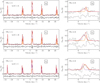 |
Fig. F.5 Same as Fig. F.2, but for core L694-2. |
| In the text | |
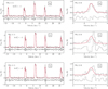 |
Fig. F.6 Same as Fig. F.3, but for core L429. |
| In the text | |
Current usage metrics show cumulative count of Article Views (full-text article views including HTML views, PDF and ePub downloads, according to the available data) and Abstracts Views on Vision4Press platform.
Data correspond to usage on the plateform after 2015. The current usage metrics is available 48-96 hours after online publication and is updated daily on week days.
Initial download of the metrics may take a while.