Fig. 5
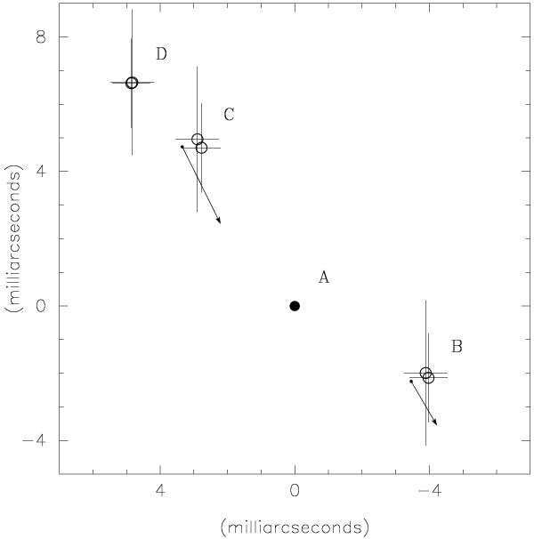
Schematic diagram showing the positions of the four components seen in the 5 GHz images shown in Fig. 1. Open circles represent the positions of the centroids of B, C, and D with respect to A in the epochs 1997.6 and 2009.4. Error bars correspond to 20% of the beam sizes. The arrows indicate the direction of the components’ displacements. The length of each arrow is proportional to the magnitude of the respective displacement.
Current usage metrics show cumulative count of Article Views (full-text article views including HTML views, PDF and ePub downloads, according to the available data) and Abstracts Views on Vision4Press platform.
Data correspond to usage on the plateform after 2015. The current usage metrics is available 48-96 hours after online publication and is updated daily on week days.
Initial download of the metrics may take a while.