![\begin{figure}
\par\includegraphics[width=17cm,clip]{7582fig1.eps}
\end{figure}](/articles/aa/full/2007/45/aa7582-07/Timg24.gif) |
Figure 1: Overview of the ALADDIN infrastructure. A 40-m rotating truss bearing the siderostats is mounted on a 30-m high structure (not represented). The light beams collected by the two siderostats are fed into off-axis telescopes and routed towards the nulling instrument cryostat by fixed relay optics (only five reflections outside the cryostat). |
| Open with DEXTER | |
In the text
 |
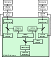
Figure 2: Block diagram of the ALADDIN optical architecture. Feed-back signals driving the control of the tip-tilt and OPD parameters are shown in dashed lines. The entrance windows of the cold enclosure are not represented, for simplicity. |
| Open with DEXTER | |
In the text
 |
Figure 3: Simulated performance of ALADDIN in terms of exozodiacal disc detection for four typical Darwin targets. The baseline design for ALADDIN has been used (see Table 3), assuming an integration time of 30 min, an uncertainty of 1% on the knowledge of the stellar angular diameter, and using the worst-case scenario for atmospheric turbulence (see text). The two vertical lines indicate the baseline range proposed for the ALADDIN conceptual design. |
| Open with DEXTER | |
In the text
 |
Figure 4: Simulated performance of ALADDIN in terms of exozodiacal disc detection for various assumptions on the uncertainty on the stellar angular diameters. |
| Open with DEXTER | |
In the text
 |
Figure 5:
Simultaneous fit of the
stellar radius and the exozodiacal density level using ten 30-min observations of a K0V star at
5 pc (actual radius of
|
| Open with DEXTER | |
In the text
 |
Figure 6: Simulated performance of ALADDIN in terms of exozodiacal disc detection for increasing integration times. |
| Open with DEXTER | |
In the text
 |
Figure 7: Simulated performance of ALADDIN in terms of exozodiacal disc detection for three different pupil diameters (50 cm, 1 m and 2 m). |
| Open with DEXTER | |
In the text