A&A 467, 49-62 (2007)
DOI: 10.1051/0004-6361:20066379
A. Mazure1 - C. Adami1 - M. Pierre2 - O. Le Fèvre1 - S. Arnouts1 - P. A. Duc2 - O. Ilbert3 - V. LeBrun1 - B. Meneux1,4,5 - F. Pacaud2 - J. Surdej3 - I. Valtchanov6
1 - LAM, Traverse du siphon, 13012 Marseille, France
2 -
DAPNIA/SAp, CEA Saclay, 91191 Gif-sur-Yvette, France
3 -
Institut d'Astrophysique et de Géophysique, Université de Liège, 17
Allée du 6 Août, B5C, 4000 Sart Tilman, Belgique
4 -
INAF - IASF, via Bassini 15, 20133 Milano, Italy
5 -
INAF, Osservatorio Astronomico di Brera, via Bianchi 46,
23807 Merate (LC), Italy
6 -
Herschel Science Centre, ESA, European Space Astronomy Centre (ESAC),
Villafranca del Castillo, PO Box 50727, Madrid 28080, Spain
Received 11 September 2006 / Accepted 13 February 2007
Abstract
Aims. We investigate structures in the D1 CFHTLS deep field to test the method that will be applied to generate homogeneous samples of clusters and groups of galaxies in order to constrain the cosmology and detailed physics of groups and clusters.
Methods. An adaptive kernel technique was applied to galaxy catalogues. This technique needs none of the usual a-priori assumptions (luminosity function, density profile, colour of galaxies) made with other methods. Its main drawback (decrease in efficiency with increasing background) is overcome by the use of narrow slices in photometric redshift space. There are two main concerns in structure detection. One is false detection and the second, the evaluation of the selection function in particular if one wants complete samples. We deal with the first concern using random distributions. For the second, comparison with detailed simulations is foreseen but we used a pragmatic approach by comparing our results to GalICS simulations to check that our detection number is not totally at odds with cosmological simulations. We used the XMM-LSS survey and secured VVDS redshifts up to ![]() to check individual detections.
to check individual detections.
Results. We show that our detection method is basically able to recover 100![]() of the C1 XMM-LSS X-ray detections (in the regions in common) in the correct redshift range plus several other candidates. Moreover, when spectroscopic data are available, we confirm our detections, even those without X-ray data.
of the C1 XMM-LSS X-ray detections (in the regions in common) in the correct redshift range plus several other candidates. Moreover, when spectroscopic data are available, we confirm our detections, even those without X-ray data.
Key words: galaxies: clusters: general
Considering groups and clusters of galaxies as cosmological probes, two
questions are still being asked: when these structures were formed and
could they constrain model universes if we consistently count them with
redshift and mass. Obviously, both questions point out the need for
complete samples of clusters and groups to answer them. Moreover, once
these samples are available, the detailed physics of galaxy groups and clusters
can be studied.
With the CFHTLS survey (Canada-France Hawaii Telescope Legacy Survey, see
http://www.cfht.hawaii.edu/Science/CFHLS) this could be done up to ![]() extending e.g. recent GEMS study (Forbes et al. 2006) on nearby groups.
extending e.g. recent GEMS study (Forbes et al. 2006) on nearby groups.
Physically, groups and clusters are deep gravitational potential wells containing dark matter, hot gas, and galaxies. Each of these components could then be used to detect their parent host.
We took advantage of both excellent multi-wavelength photometry from CFHTLS and very large samples of spectra (VVDS survey: VIMOS VLT Deep Survey, Le Fèvre et al. 2005) to define these very good photometric redshifts in the CFHTLS D1 field, so we exploit them here to search for structures in that field. We postpone the use of counts of structures to constrain cosmological parameters to another paper in which all the CFHTLS fields will be analysed. Indeed, only a few systems are expected in less than 1 square degree. Instead, we stress how the method appears efficient. In particular, a close comparison to the X-ray detections done in the framework of the XMM-LSS survey (e.g. Pierre et al. 2006) shows very good agreement when taking biases in both methods into account and we will also explain this comparison using secured VVDS redshifts.
Section 2 is about data and methods. Section 3 describes the structure
detection and the resulting reliability. Finally, Sect. 4 is the conclusion.
We use the following cosmological parameters:
H0 = 67 km s-1 Mpc-1,
![]() and
and
![]() in order to be coherent with the GalICS simulations.
in order to be coherent with the GalICS simulations.
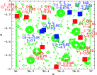 |
Figure 1:
Masked regions following the CFHTLS recipe on the D1 field with the
XMM detections
superimposed. Red filled squares are the C1 XMM-LSS clusters and blue ones
are the C2 and C3. We also give the name of the XMM-LSS cluster (see
Pierre et al. 2006), as well as its redshift and bolometric X-ray
luminosity in 1044 erg/s within R500. |
| Open with DEXTER | |
The catalogues (publicly available and fully described at
http://terapix.iap.fr) used for the detection and the
characterisation of the structures have been obtained within the framework of the
CFHT Legacy Survey (i.e. MEGACAM ![]() ,
g', r', i', z' data) for the so-called
D1 deep field. We used the i' band to detect our structures (see below).
,
g', r', i', z' data) for the so-called
D1 deep field. We used the i' band to detect our structures (see below).
For the photometric redshift calculations, photometry (BVRI) obtained in the framework of the VVDS survey (Le Fèvre et al. 2005), as well as Spitzer data, are also used (see Ilbert et al. 2006, for details). In a few words, photometric redshifts were obtained by adjusting spectral energy distribution of galaxy templates, which are iteratively modified in terms of flux zero points and continua shapes using a set of high-quality spectroscopic redshifts issued from the VVDS (see Ilbert et al. 2006). A very good accuracy was obtained between z = 0.2 and z=1.2 and for i' = 24.5 (the present limit of our sample, see below) as described in Ilbert et al. (2006): in a photometric/spectroscopic redshift plot, the standard deviation is 0.04 in redshift.
Once the structures are identified with their galaxy content (see following sections), we look for spectroscopic data in the VVDS catalogue both to confirm our detections and to give an estimate of the velocity dispersion if possible. However, the VVDS does not cover the entire D1 field and is characterised by an inhomogeneous sampling rate; and it avoids peculiar masked regions (distinct from the CFHTLS D1 masked regions, however), so several systems have only a few spectroscopic measurements or not at all.
On the other hand, the XMM-LSS (Pierre et al. 2006) provides for the CFHTLS D1
covered area, a catalogue of candidate structures classified in several classes
(C1, C2, C3) with confirmed spectroscopic redshifts (independently from VVDS redshifts).
Class 1 (C1) is defined as sources with no contamination by point sources
interpreted as extended ones. Class 2 (C2) corresponds to a contamination
of 50![]() and class 3 (C3) to highly contaminated ones (see Pierre et al. 2006, for
more details). We also used the identifications by
Willis et al. (2005) and Andreon et al. (2005) of specific systems with the
same X-ray data.
and class 3 (C3) to highly contaminated ones (see Pierre et al. 2006, for
more details). We also used the identifications by
Willis et al. (2005) and Andreon et al. (2005) of specific systems with the
same X-ray data.
First of all, Fig. 1 shows the CFHTLS D1 masked regions due to bright stars and the CCD defects of the optical data. Masked regions are represented by the spurious objects that were detected inside. Rings made by agglomerated points with empty centres are for example due to stars that shield part of the sky (i.e. empty centres) and contamine the immediate vicinity with their diffuse light (e.g. rings of points).
It allowed us to check whether an XMM source is found in a masked region and then if any optical detection could be spoiled by this masking (e.g. XLSSC 029 at the upper left edge of the D1 Megacam field). Second, we give the various XMM-LSS fields in Fig. 2 along with their corresponding associated exposure times (which can vary by a factor of 2) and the C1, 2, and 3 cluster detections. The part of the field at both small right ascension and declination with no XMM observations at all is called the "Absence zone'' in the following.
The method is based on the simple detection of contrasts in numerical density maps of galaxies computed using i' band data. But, to eliminate fore and background contaminations as much as possible, these density maps are built in redshift (distance) slices. The technique used to compute the galaxy density maps is the well-known adaptive kernel method; see e.g. Dressler & Shectman (1988), Beers et al. (1991) for seminal works and also Biviano et al. (1996) for a detailed application and discussion of significance. It has the advantage over wavelets (e.g. Escalera et al. 1992; Slezak et al. 1994) of not needing reconstruction of the structures using the whole range of scales and is less affected by edge effects. Edge effects, as well as mask effects (masks due for example to the presence of bright stars in the field), are taken into account neither by mirroring the data nor by adding randomly distributed points. We compared our detections with the map of masks and eyeballed if there was any unfortunate coincidence. Systems where the centre of the contours was in such a masked region were flagged by an (M) in the lists of candidates, if not already associated with an X-ray structure.
In this testing approach, we prefer to deal with crude artefacts rather than smoothing them in order to estimate their effects when compared to totally different detection methods. In an application aimed at counting groups and clusters to constrain cosmology, it turns out that the best way would be to, a posteriori, totally exclude masked regions as done e.g. when using lensing techniques. For the edge effects, comparison of our detections with real structures detected in X-ray will indicate later that the effect does not seem to be very strong. Again, when counting structures, this should be taken into account by removing adequate border zones. Only foreseeing a comparison with simulations, including fake structures where completeness in terms of richness or mass is well-controlled, will allow quantitative estimates of these effects.
We thus defined overlapping slices with a width of 0.1 in photometric
redshift all along the line of sight. An overlap of 0.05 was chosen, as real
structures are often expected to show up in adjacent slices.
The D1 field is 0.8 deg2 (taking into account the masked area rejection)
and we define a grid of
![]() pixels on it. The pixel size (
pixels on it. The pixel size (![]() 0.3 arcmin)
corresponds to
0.3 arcmin)
corresponds to ![]() 80/120/160 kpc at z=0.25/0.5/1 and is kept fixed with
redshift.
80/120/160 kpc at z=0.25/0.5/1 and is kept fixed with
redshift.
 |
Figure 2: Regions observed by XMM with the corresponding C1, C2, and C3 detections as in Fig. 1 (see Pierre et al. 2006). The red circles have a shorter X-ray exposure time. Red filled squares are the C1 XMM-LSS clusters and blue ones are the C2 and C3. |
| Open with DEXTER | |
To establish statistical significance, we used a bootstrap technique both on the real data and simulations. For each new realisation of a given galaxy distribution obtained by the bootstrap technique, we built the corresponding density map, and clustered points on small scales stay clustered but are spread out. Points that are unclustered or clustered on larger scales are also spread out. Then, taking the mean of several density maps leads to erase fluctuations and flattens the mean background, keeping clustering present. This flattening added to the removal of distant (or nearby) clustering due to the use of narrow slices allows using random distributions to evaluate false detections, at least when using high-value thresholds. In practice, a mean bootstrapped map of the galaxy distribution within a given zphot slice is obtained using 1000 bootstrap resamplings (see e.g. Biviano et al. 1996, for a complete description).
 |
Figure 3: Identification distance in arcmin between two detections (in successive redshift slices) that are assumed to be the same structure as a function of redshift. Solid and dashed lines are (in arcmin) the 1 and 2 Mpc values as a function of redshift. |
| Open with DEXTER | |
Table 1: Number of peaks detected per square degree in 100 random fields with respect to a given threshold.
Table 2: Number of peaks detected per square degree in 50 GalICS fields (averaged over the 50 available fields) and in real D1 fields (rescaled to 1 deg2) with respect to redshift and to a given threshold. We only give the non-overlapping redshift slices.
The present analysis was performed with the i' band CFHLS catalogue, down to the magnitude limit i' = 24.5, which encompasses the typical i'* of the luminosity function at z=1 (e.g. Adami et al. 2005) and which ensures a good compromise between using the reddest possible band and the best quality photometric data.
We applied the technique to overlapping slices with central redshifts between 0.2 and 1.2 (where the quality of photometric redshifts is optimal). We added the slice 0.10-0.20 to check if the nearby C1/0.041 is detected by our method. We also give the tentative detections up to z=1.5 in the appendix, but these results are still uncertain due to the decrease in the photometric redshift accuracy after z=1.2. This is also why the last redshift slice in the appendix was taken larger (width of 0.15 in redshift) than the other ones.
Once the mean image is computed (from 1000 realisations obtained by bootstrapping the actual data), the peaks are detected. This detection uses the classical image analysis with Sextractor (Bertin & Arnouts 1996) where the internal parameters are adapted to the pixel size with at least 2 pixels above the chosen threshold (3 or 4). As in the usual image analyses, structures are detected with respect to their background (estimated globally in Sextractor), which defines a threshold (peak density over background density). Positions and best ellipse fitting (orientation and axes ratio) are derived by adopting 1 Mpc as the size of the semi-major axis of these structures.
A catalogue of structures for each redshift slice was then generated. We also selected individual galaxies potentially belonging to each structure as for all galaxies included in the considered redshift slice and in the 1 Mpc semi-major axis ellipse. For a given structure, these lists still include, however, interloper galaxies that have positions inside the structure ellipse but are the foreground or background galaxies included in the redshift slice. This is due to the photometric redshift uncertainty (see Ilbert et al. 2006).
We avoided the very low redshift slices because, in that case, the number of expected structures is small due to the small solid angle, and the reliability of photometric redshifts is degraded (see Ilbert et al. 2006). We also provide detections only up to z=1.2(tentative detections up to z=1.5 are only given in appendix), but we clearly waited for complete comparison with the next generation of simulations to validate and study detections of the most distant candidate clusters in terms of mass. As we used galaxy as tracers of structures, it is important to deal with large-scale structure simulations that include a well-controled implementation of galaxies and not only of DM. It is, however, encouraging that the number of detections agree closely with generic GalICS predictions (see below).
Table 3: Structures detected in redshift slices with central redshift from 0.15 to 0.70.
Table 4: Structures detected in redshift slices with central redshift from 0.75 to 1.05.
Table 5: Structures detected in redshift slices with central redshift from 1.10 to 1.20.
Table 6: Main structures detected (with available VVDS spectroscopic data).
Every significant (i.e. in terms of threshold, see below) structure is
labelled with an identification in every slice, as well as a general identification.
Some structures could show up at almost the same positions in several
slices. To identify these multiple detections, we chose to offer a
single identification when two detections in adjacent redshift slices had
overlapping ellipses on the sky. We show in Fig. 3 the
coordinate differences
of all multiple detections in successive redshift slices. This figure shows
that two successive detections are always closer than 2 Mpc (by definition) and
that more than 75![]() are closer than 1 Mpc. The values are roughly 2 times (or
smaller) the usual virial radius, which ensures that, most of
the time, we are not merging unrelated structures. The other
detections of a given structure are then labelled by the same number but
flagged by parentheses in Tables 3 to 5, which
summarise the structures we found.
are closer than 1 Mpc. The values are roughly 2 times (or
smaller) the usual virial radius, which ensures that, most of
the time, we are not merging unrelated structures. The other
detections of a given structure are then labelled by the same number but
flagged by parentheses in Tables 3 to 5, which
summarise the structures we found.
We note, however, that when a structure (e.g. large-scale structure line-of-sight filaments) is percolating through a large number of redshift slices, the position of the lowest redshift detection can be quite different from the one in the highest redshift slice. We also note that C1-029 from Pierre et al. (2006) is just on the edge of the D1 field of view and is also located in a masked region. It is perhaps identified with cluster 35 (general ID of the tables), but this remains very uncertain.
Finally, since part of the D1 field is covered by VVDS data, we used the spectroscopic information. In every 1 Mpc ellipse, when available, we looked at spectroscopic data in the 0.1 width redshift range to confirm that the local zdistribution exhibits any compactness in the velocity space compatible with the presence of possible real structures. We looked at galaxies along the line of sight in the considered slice separated by gaps of less than 0.0026, so as to use the same gap as in Adami et al. (2005) on similar spectroscopic data. These gaps were adapted to redshift using the (1 + z) dependence.
We deal with false detections as follows. We generate 100 independent slices with 5000, 8000, and 11 000 randomly distributed points (these numbers are representative of numbers of galaxies in real redshift slices as shown in Tables 3 to 5), and we analyse these slices in the same way as real ones. We compute the number of detections depending on the detection thresholds used.
As we proceed in narrow slices, the effect of distant clustering that diminishes the contrast of real structures is also strongly diminished just as well as the bootstrapping does, so mean random fields represent fairly well the actual slice background.
Table 1 shows the numbers of detections in a given slice (whatever
the redshift) with respect to the threshold defined in terms of 3 and
4![]() of the background. This table then estimates the
level of wrong structure detections for a given slice.
This level remains modest, since there is at most 2 in a given slice at
the 3
of the background. This table then estimates the
level of wrong structure detections for a given slice.
This level remains modest, since there is at most 2 in a given slice at
the 3![]() level and 1 at the 4
level and 1 at the 4![]() level.
level.
As a first step we generate, using the 50 available GalICS simulations (with H0=67 km s-1 Mpc-1,
![]() and
and
![]() ),
slices with the same widths as the ones with real data; e.g. Meneux et al.
or Blaizot et al. (2006) for a discussion of the ability of these simulations
to represent the real universe. These simulations are representative of
the general clustering in the whole Universe with the same depth as our
sample. For each GalICS slice, we produce mean bootstrapped maps in the same
conditions as for real data. In the present stage (see below), we will simply
use these simulations to check that the used thresholds lead to a number
of detections (see Table 2) that is not totally at odds with
the one provided by the real fields.
Of course, as well in real data as in simulated ones, false detections (due
e.g. to projection effects) and cosmic variance affect the number of
structures. Consequently, numbers are expected to agree only in the mean and
we recall that a complete evaluation in terms of
richness, mass, and other characteristics will be the subject of another paper.
),
slices with the same widths as the ones with real data; e.g. Meneux et al.
or Blaizot et al. (2006) for a discussion of the ability of these simulations
to represent the real universe. These simulations are representative of
the general clustering in the whole Universe with the same depth as our
sample. For each GalICS slice, we produce mean bootstrapped maps in the same
conditions as for real data. In the present stage (see below), we will simply
use these simulations to check that the used thresholds lead to a number
of detections (see Table 2) that is not totally at odds with
the one provided by the real fields.
Of course, as well in real data as in simulated ones, false detections (due
e.g. to projection effects) and cosmic variance affect the number of
structures. Consequently, numbers are expected to agree only in the mean and
we recall that a complete evaluation in terms of
richness, mass, and other characteristics will be the subject of another paper.
 |
Figure 4:
Number of 3 |
| Open with DEXTER | |
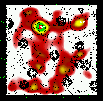 |
Figure 5:
Slice 0.10-0.20 (i.e.
|
| Open with DEXTER | |
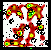 |
Figure 6: Same as Fig. 5 for the slice 0.15-0.25. |
| Open with DEXTER | |
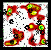 |
Figure 7: Same as Fig. 5 for the slice 0.20-0.30. |
| Open with DEXTER | |
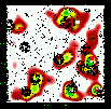 |
Figure 8: Same as Fig. 5 for the slice 0.25-0.35. |
| Open with DEXTER | |
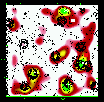 |
Figure 9: Same as Fig. 5 for the slice 0.30-0.40. |
| Open with DEXTER | |
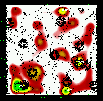 |
Figure 10: Same as Fig. 5 for the slice 0.35-0.45. |
| Open with DEXTER | |
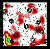 |
Figure 11: Same as Fig. 5 for the slice 0.40-0.50. |
| Open with DEXTER | |
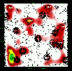 |
Figure 12: Same as Fig. 5 for the slice 0.45-0.55. |
| Open with DEXTER | |
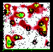 |
Figure 13: Same as Fig. 5 for the slice 0.50-0.60. |
| Open with DEXTER | |
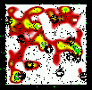 |
Figure 14: Same as Fig. 5 for the slice 0.55-0.65. |
| Open with DEXTER | |
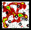 |
Figure 15: Same as Fig. 5 for the slice 0.60-0.70. |
| Open with DEXTER | |
We, however, compare the number of detections in our sample and in the GalICS
simulations from Table 2 and Fig. 4.
This will give a global estimate
of how closely our detections agree with the cosmological model
used in the chosen GalICS simulations. Figure 4 shows that
our number of detections does agree with the (
![]() and
and
![]() )
model given the error bar sizes.
Of course these detections could be in both cases either real or false
detections. However, using the random fields representative
of each slice background, as seen above, the high-level thresholds show that the
false detection rate is expected to be rather low. It would be an unlikely
coincidence that in every slice, the number of real and false detections
conspire to give the right numbers.
)
model given the error bar sizes.
Of course these detections could be in both cases either real or false
detections. However, using the random fields representative
of each slice background, as seen above, the high-level thresholds show that the
false detection rate is expected to be rather low. It would be an unlikely
coincidence that in every slice, the number of real and false detections
conspire to give the right numbers.
We detect less structures at intermediate redshifts (0.55; 0.75) than predicted by the model. But this also corresponds (see below) to a lack of X-ray detections, revealing that it could be an empty region. More precise comparisons are required to constrain the Cosmology, but the relatively good agreement between simulations and observations gives confidence in the method.
As seen from Tables 3 to 5, we
detected about 40 independent structures within an area of
0.8 deg2 up to z=1.1, which is very close to the ![]() per deg2 found by Olsen
et al. (2007) using a totally different method and a slightly deeper magnitude
limit; but given the considered magnitudes, this should only affect the faint
population of our detected structures and not the structures
themselves too strongly. A close comparison between the two methods is
devoted to another paper.
per deg2 found by Olsen
et al. (2007) using a totally different method and a slightly deeper magnitude
limit; but given the considered magnitudes, this should only affect the faint
population of our detected structures and not the structures
themselves too strongly. A close comparison between the two methods is
devoted to another paper.
Once false detection problem has been addressed, the next concern is the ability of any method to detect real structures at the right place and at the right distance or instead to explain when and why they are not detected. In other words, what is the so-called detection function?
One way to correctly estimate such a selection function is to use cosmologically simulated catalogues analysed with exactly the same protocol as for the real data. One can also use mock catalogues in which structures are put in by hand allowing the recovery power estimation. However, if it is pedagogical in the sense that it gives a sense of how the algorithm works, it is not always possible to explore all the range of parameters and conditions in a practical way until detailed cosmological simulations adapted to the CFHTLS characteristics are available.
A second way to estimate this selection function is empirical: the
use of detections obtained in a totally different way (X-ray emission
of groups and clusters detected by the XMM-LSS) accounting in the meantime
for spectroscopic information issued from VVDS. This spectroscopic
information is used in the following way. For every structure in a given
slice, we look at the redshift distribution of the VVDS data along the line
of sight, within
a 1 Mpc ellipse, up to z =1.2 (central redshift of the highest redshift
slice considered) and we look for clustering in spectroscopic
redshift within the redshift range of the slice. We put galaxies as
possible members of a system when the redshifts of 2 galaxies do not differ
by more than 0.0026 ![]() (1 + z) (see also Sect. 3.1). All the
corresponding numbers of this analysis are given in Table 6.
(1 + z) (see also Sect. 3.1). All the
corresponding numbers of this analysis are given in Table 6.
Here, we check if we recover with the thresholds defined above the various XMM sources or not. Of course, there are physical reasons for not detecting an optical overdensity in X-ray (e.g. if dealing with a non totally virialized system), as well as observational ones since XMM-LSS does not entirely cover D1 and does not have a completely homogeneous exposure time. Conversely, if there is no optical structure when a diffuse X-ray source is present, it could reveal a failure of the present method or a mistake in its distance, as well as a peculiar class of extended X-ray structures (as fossil groups that are massive systems with few galaxies, e.g. Jones et al. 2003 or Ulmer et al. 2005).
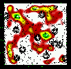 |
Figure 16: Same as Fig. 5 for the slice 0.65-0.75. |
| Open with DEXTER | |
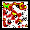 |
Figure 17: Same as Fig. 5 for the slice 0.70-0.80. |
| Open with DEXTER | |
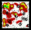 |
Figure 18: Same as Fig. 5 for the slice 0.75-0.85. |
| Open with DEXTER | |
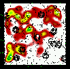 |
Figure 19: Same as Fig. 5 for the slice 0.80-0.90. |
| Open with DEXTER | |
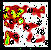 |
Figure 20: Same as Fig. 5 for the slice 0.85-0.95. |
| Open with DEXTER | |
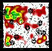 |
Figure 21: Same as Fig. 5 for the slice 0.90-1.00. |
| Open with DEXTER | |
Figures 5 to 23 show a subsample of
the slices up to z = 1.1 for thresholds of 3![]() .
We note that these
figures are plotted with the same colour coding, with the lowest level being
the mean value of the density map. If different slices exhibit strongly
different background noise (or different maximal density values), then
significant peaks can appear less prominent in the figures compared to less
significant peaks in slices with different noise levels. The individual
properties of the structures are given in Tables 3 to
5. We note that structure 35
(general identification) is present from z=0.85 to z=1.25 with a small
position shift on the sky. Structure 29 (general identification) is perhaps
identified with the C3-c cluster (Pierre et al. 2006), but the case is not closed
as it is located very close to a masked region.
We overplotted XMM-LSS clusters in the range 0.1-1.2 with the
following rule: C1, C2, and C3 XMM-LSS clusters were plotted in our
graphs when included in the considered photometric redshift range (with
an allowance of 0.01, only useful for C1-025).
.
We note that these
figures are plotted with the same colour coding, with the lowest level being
the mean value of the density map. If different slices exhibit strongly
different background noise (or different maximal density values), then
significant peaks can appear less prominent in the figures compared to less
significant peaks in slices with different noise levels. The individual
properties of the structures are given in Tables 3 to
5. We note that structure 35
(general identification) is present from z=0.85 to z=1.25 with a small
position shift on the sky. Structure 29 (general identification) is perhaps
identified with the C3-c cluster (Pierre et al. 2006), but the case is not closed
as it is located very close to a masked region.
We overplotted XMM-LSS clusters in the range 0.1-1.2 with the
following rule: C1, C2, and C3 XMM-LSS clusters were plotted in our
graphs when included in the considered photometric redshift range (with
an allowance of 0.01, only useful for C1-025).
In the tables, when a given structure is detected in adjacent slices, we always selected the one corresponding to the highest significance level to identify it with an X-ray source. The X-ray position has to be included in the optical detection ellipse. Finally, in the tables, we also take into account the XMM-LSS clusters provided by Andreon et al. (2005) and Willis et al. (2005) in specific analyses, separate from Pierre et al. (2006), but using the same XMM data.
 |
Figure 22: Same as Fig. 5 for the slice 0.95-1.05. |
| Open with DEXTER | |
 |
Figure 23: Same as Fig. 5 for the slice 1.00-1.10. |
| Open with DEXTER | |
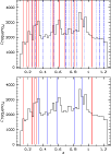 |
Figure 24: Histogram of all photometric redshifts along the line of sight between z=0.1 and 1.25 overplotted with detected structures. Upper figure: structures detected with the photometric redshifts. Those with a precise redshift determination (first from XMM-LSS papers and second from VVDS spectroscopic data) are the red continuous lines. The blue dashed lines are clusters with only the photometric redshift determination (taken as the central redshift of the considered slice). Lower figure: structures detected in X-rays from Pierre et al. (2006). C1 clusters are the red lines. C2 and C3 clusters are the blue lines. |
| Open with DEXTER | |
![\begin{figure}
\par\includegraphics[angle=270,width=16.5cm,clip,]{6379f25.ps}\end{figure}](/articles/aa/full/2007/19/aa6379-06/Timg72.gif) |
Figure 25:
Summary of the properties for the candidate 0004 in the [0.25; 0.35]
redshift slice. Lower left: |
| Open with DEXTER | |
Conversely, several structures are detected in the visible at a
significant level with no counterparts in X-ray: are they real or
false detections? Restricting ourselves to areas in common, with no biases (i.e.
excluding A, G, E, M, S regions: see Tables 3 to 5),
and limiting ourselves to ![]() (the limit in redshift of Pierre et al. 2006), we find 11 such structures of which 5 have spectroscopic
information. Namely these are systems 2, 16, 19, 21, and 28 (see
Table 6) and are therefore likely to be real. We also note that
structure number 3 (general ID) is detected at z=0.26 by Pierre et al. (2006)
and at z=0.225 using only VVDS redshifts. This discrepancy is probably due to
the small number of VVDS redshifts (4) in the considered slice, leading to a
wrong estimate.
(the limit in redshift of Pierre et al. 2006), we find 11 such structures of which 5 have spectroscopic
information. Namely these are systems 2, 16, 19, 21, and 28 (see
Table 6) and are therefore likely to be real. We also note that
structure number 3 (general ID) is detected at z=0.26 by Pierre et al. (2006)
and at z=0.225 using only VVDS redshifts. This discrepancy is probably due to
the small number of VVDS redshifts (4) in the considered slice, leading to a
wrong estimate.
We conclude that we are probably more efficient at detecting very low-mass and galaxy-dominated systems (as compared to gas or dark-matter dominated systems) than are X-ray methods. These 11, only optically-detected, structures is the number of structures probably missed by the X-ray method.
A future paper will be dedicated to precise study of the properties of these structures, but we show in Fig. 24 the histogram of all photometric redshifts along the line of sight between z=0.1 and 1.25 overplotted with detected structures. We clearly see that we can detect structures in almost all galaxy concentrations in the redshift space. We also detect several structures in low-density regions.
We also present an example of what can be done.
Figure 25 shows for example the luminosity functions in the
CFHTLS ![]() ,
g', r', i', and z' bands of the candidate 0004 in the [0.25; 0.35]
redshift slice. Objects are selected in the slice (so we still have some
foreground and background contamination by galaxies in the considered slice
thar are not physically included in the structures) and within the 1 Mpc ellipse.
It also shows the redshift and spectro-morphological type
histograms (following Coleman et al. 1980), as well as the red sequence
in the colour-magnitude relation.
,
g', r', i', and z' bands of the candidate 0004 in the [0.25; 0.35]
redshift slice. Objects are selected in the slice (so we still have some
foreground and background contamination by galaxies in the considered slice
thar are not physically included in the structures) and within the 1 Mpc ellipse.
It also shows the redshift and spectro-morphological type
histograms (following Coleman et al. 1980), as well as the red sequence
in the colour-magnitude relation.
Another remark concerns the detection of structures
in several redshift slices. Two such structures (limiting ourselves to those not
heavily polluted by CFHTLS masking candidates and to z lower than 1.05:
structures 4 and 23) extend over redshift intervals
of strictly more than 0.3 and are detected in each of the successive bins
at the 3-![]() level (see Table 7). This interval of 0.3
represents
level (see Table 7). This interval of 0.3
represents ![]() 3 times the typical photometric redshift uncertainty. It is
also also larger than the catastrophic errors. This ensures that we are
probably not dealing with artefacts. It can still be chance alignements of
real structures. However, if not, this is really a puzzling fact, as the
length of these filaments (or structure chains) is several hundred Mpc!
Their radial extension is clearly larger than the maximal void sizes computed
in Hoyle & Vogeley (2004). If these filaments are real, then they have to
cross at least one node (the place where the massive clusters form) of the
cosmic web and to percolate from a cosmic cell to another one. We should
therefore detect massive clusters inside these filaments in the XMM-LSS data,
and these are associated with X-ray structures.
3 times the typical photometric redshift uncertainty. It is
also also larger than the catastrophic errors. This ensures that we are
probably not dealing with artefacts. It can still be chance alignements of
real structures. However, if not, this is really a puzzling fact, as the
length of these filaments (or structure chains) is several hundred Mpc!
Their radial extension is clearly larger than the maximal void sizes computed
in Hoyle & Vogeley (2004). If these filaments are real, then they have to
cross at least one node (the place where the massive clusters form) of the
cosmic web and to percolate from a cosmic cell to another one. We should
therefore detect massive clusters inside these filaments in the XMM-LSS data,
and these are associated with X-ray structures.
We show in this paper that using the excellent quality photometric redshifts
computed on the D1 CFHTLS field by Ilbert et al. (2006) and combining them
with an adaptative kernel galaxy density estimate, we were able to efficiently
detect structures up to ![]() without any hypotheses on the nature of
the structures. The analysis based on
slices in redshift space allows to reduce efficiently fore and background
contamination, then increasing the contrast of real structures.
without any hypotheses on the nature of
the structures. The analysis based on
slices in redshift space allows to reduce efficiently fore and background
contamination, then increasing the contrast of real structures.
 |
Figure 26: Trichromic r/i/z CFHTLS image of candidate 0004 in the slice 0.50-0.60. The three XMM-LSS spectroscopic redshifts (distinct from the 2 VVDS redshifts) are shown. The large galaxy at the top of the image is related to the XMM-LSS C1 cluster 041 at z=0.14. |
| Open with DEXTER | |
Table 7:
Redshift detection interval of the radial filaments, mean
coordinates, X-ray association, redshift
extension in Mpc, and redshift extension in Mpc quadratically diminished
with the ![]() 1
1![]() photometric redshift uncertainty at the given
redshift.
photometric redshift uncertainty at the given
redshift.
Our detections, taking biases of both analyses into account, are in good agreement with X-ray detections (and sometimes help to recover them) and also allowed low mass structures, invisible for X-ray surveys, to be detected. Detections with no evident X-ray counterpart are in general confirmed by spectroscopic information when available. The efficiency of the method also seems to be due to the fact that light appears to trace mass in clusters, which has been verified at least for low redshifts (e.g. Katgert et al. 2004). It is then encouraging to use our method in parallel with others to count clusters both in simulationswith realistic galaxy representation and in the real universe. We detected at least two structure-chains of several hundreds of Mpc (structures 4 and 23). The size of the D1 field is, however, far too small to conduce quantitative cosmological studies, but it allowed calibration of our method. Such quantitative studies will be achieved in future works using other large-scale and deep CFHTLS fields.
Acknowledgements
The authors thank C. Benoist and L.F. Olsen for useful discussions. This work is based in part on data obtained with the European Southern Observatory in Paranal, Chile, and on observations obtained with MegaPrime/Megacam, a joint project of the CFHT and CEA/DAPNIA, at the Canada France Hawaii Telescope (CFHT), which is operated by the National Research Council (NRC) of Canada, the Institut National des Science de l'Univers of the Centre National de la Recherche Scientifique (CNRS) of France, and the University of Hawaii. This work is based in part on data products produced at TERAPIX and the Canadian Astronomy Data Centre as part of the Canada-France-Hawaii Telescope Legacy Survey, a collaborative project of NRC and CNRS. This work is based in part on observations obtained with XMM-Newton, an ESA science mission with instruments and contributions directly funded by ESA Member states and NASA. The VLT-VIMOS observations were carried out on guaranteed time (GTO) allocated by the European Southern Observatory (ESO) to the VIRMOS consortium, under a contractual agreement between the Centre National de la Recherche Scientifique of France, heading a consortium of French and Italian institutes, and ESO, to design, manufacture, and test the VIMOS instrument.
Table A.1: Same as Tables 3 to 5 for slices with central redshifts between 1.25 to 1.425.