 |
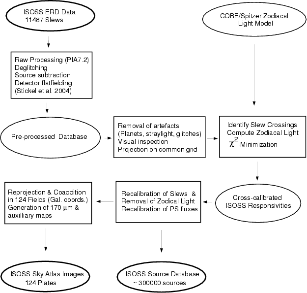
Figure 1: Flow diagram summarizing the processing steps of the ISOSS slew data from the raw data streams to the final ISOSS Sky Atlas images and the ISOSS compact source database. |
| Open with DEXTER | |
In the text
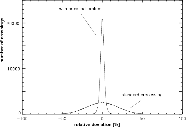 |
Figure 2: The distribution of the relative differences of slew brightnesses at slew crossings. The width of the distribution after rescaling is an order of magnitude narrower than the original distribution obtained with the standard processing. |
| Open with DEXTER | |
In the text
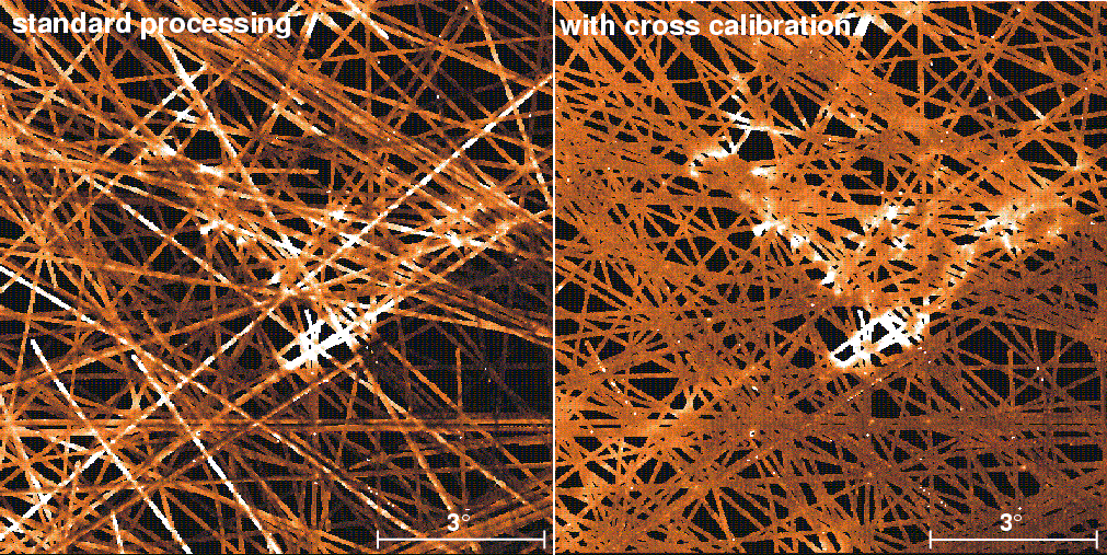 |
Figure 3:
A
|
| Open with DEXTER | |
In the text
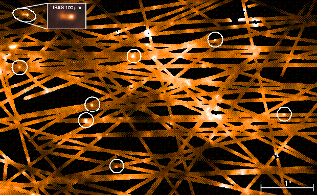 |
Figure 4:
An example of a map assembled from the rescaled ISOSS slew data. The image shows a typical sky region in the northern galactic hemisphere in Cygnus. Sources appearing in the ISOSS compact source database (Stickel et al. 2003,2002) are encircled. The ellipse ( upper left) indicates a close double source and the rectangular inset the corresponding region from the IRAS 100 |
| Open with DEXTER | |
In the text
![\begin{figure}
\par\resizebox{8.5cm}{!}{\includegraphics[origin=c,angle=-90]{6236fig6.ps}}\end{figure}](/articles/aa/full/2007/18/aa6236-06/img34.gif) |
Figure 5:
Map of M 31 derived from all Serendipity Survey slews crossing the area. The large scale ring structure and the bright knot north-west of the center is apparent. (Cf. the fully sampled ISOPHOT 170 |
| Open with DEXTER | |
In the text
![\begin{figure}
\par\includegraphics[width=17cm]{6236fig7.ps}\end{figure}](/articles/aa/full/2007/18/aa6236-06/img36.gif) |
Figure 6:
The overall distribution of the coldest cores (crosses) with
ISOSS 170 |
| Open with DEXTER | |
In the text
![\begin{figure}
\par\includegraphics[width=8.2cm,clip]{6236fig8.ps}\end{figure}](/articles/aa/full/2007/18/aa6236-06/img41.gif) |
Figure 7:
Far-infrared emission from dust in the region
of Cassiopeia A. The ISOPHOT 170 |
| Open with DEXTER | |
In the text