 |
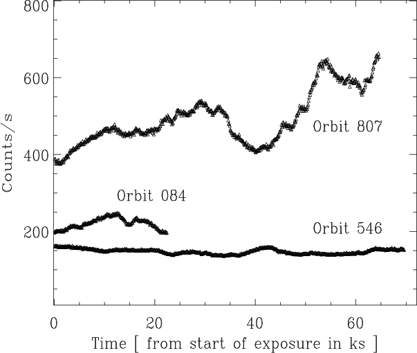
Figure 1: Background subtracted, 0.6-10 keV PN light curves of Mrk 421 with time binning of 100 s. Times are counted from the beginning of the actual exposure. The curves are labeled by the orbit of the observation. |
| Open with DEXTER | |
In the text
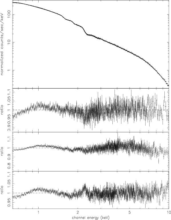 |
Figure 2: Broken power law model fit to the 0.6-10 keV data during the three observations. The two top figures show the fit and the data to model ratio for orbit 84, the middle panel the ratio for orbit 546, the bottom panel that for orbit 807. |
| Open with DEXTER | |
In the text
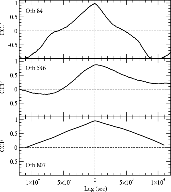 |
Figure 3: CCF plots for the orbit 84 ( top), orbit 546 ( middle) and orbit 807 ( bottom) observation. The 10 s binned soft and hard band light curves for the total observations were used; the error bars are smallerthan the symbol sizes. The curves are labeled by the orbit of theobservation. |
| Open with DEXTER | |
In the text
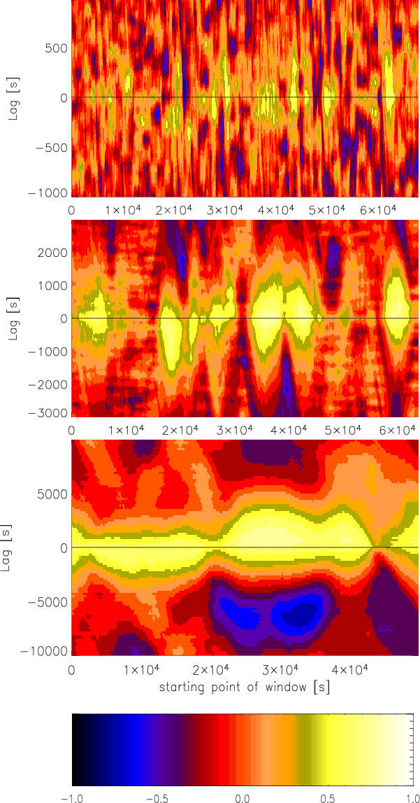 |
Figure 4: Sliding window CCFs for orbit 546. The amplitude of the CCF is color coded, with lags plotted in the vertical direction. The top figure was calculated with an individual data length of 2000 s, the middle with 6000 s, and the bottom figure with 20 000 s long data streams. The bottom panel shows the color bar used for the numerical values of the CCFs for the above figure and for Fig. 6. |
| Open with DEXTER | |
In the text
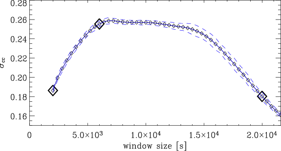 |
Figure 5:
Standard deviations
|
| Open with DEXTER | |
In the text
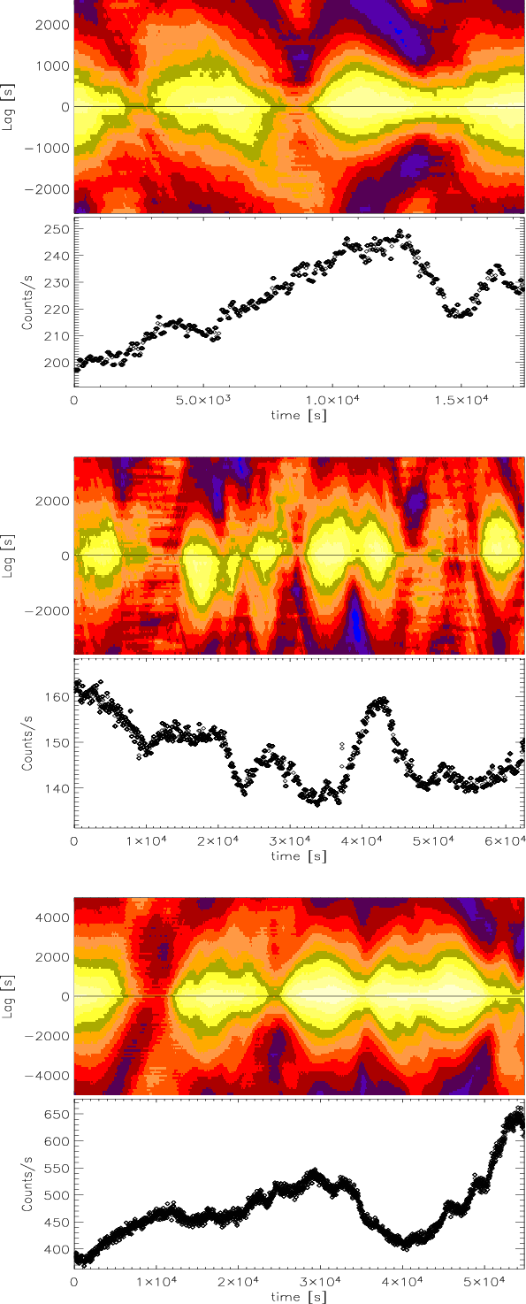 |
Figure 6: Sliding window CCFs for orbits 084 ( top), orbit 546 ( middle) and orbit 807 ( bottom) calculated with the optimized sliding window lengths (see text). The amplitude of the CCF is color coded, with lags plotted in the vertical direction. Plotted below the individual CCFs are the corresponding light curves in the total (0.6-10 keV) energy band. The x-axis is the time from the beginning of the observation which, for the CCFs, corresponds to the start time of the data window for the calculations. |
| Open with DEXTER | |
In the text
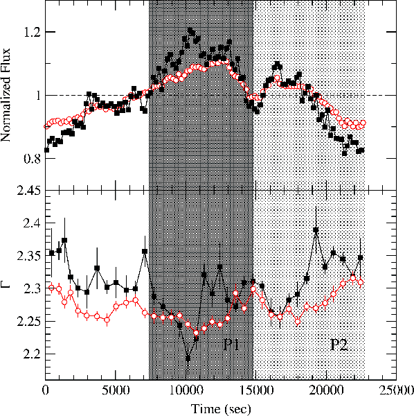 |
Figure 7:
Background subtracted, 0.6-2 and 4-10 keV PN light curves
of Mrk 421 in orbit 84 (open circles and filled squares, respectively), in
bins of size 200 s ( top panel). The light curves are normalized to their
mean. The corresponding
|
| Open with DEXTER | |
In the text
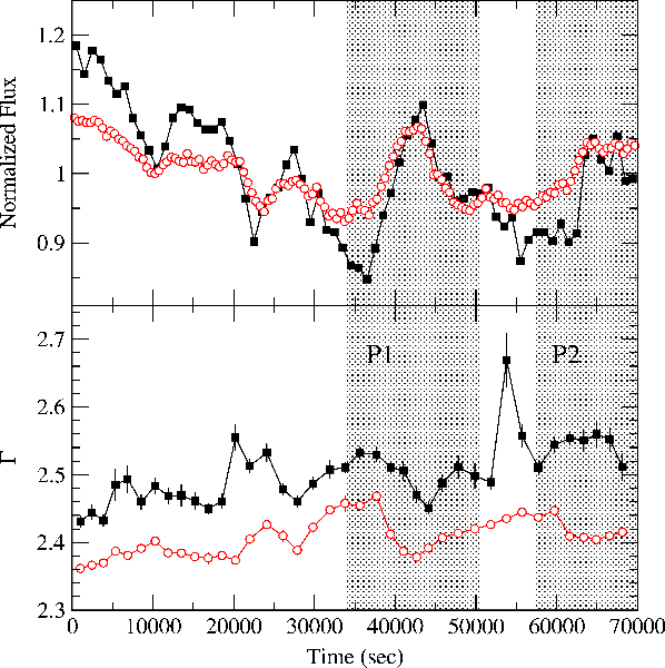 |
Figure 8: Same as Fig. 7, but for the observation during orbit 546. The hard band and soft band count rate light curves are in bins of size 1000 s and 500 s, respectively. |
| Open with DEXTER | |
In the text
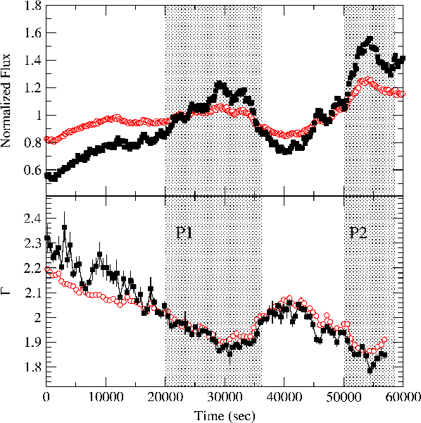 |
Figure 9: Same as Fig. 7, but for the observation during orbit 807. The count rate light curves are in bins of size 40 s. |
| Open with DEXTER | |
In the text
![\begin{figure}
\par\includegraphics[width=8.5cm,clip]{2767fg10.eps}\end{figure}](/articles/aa/full/2005/44/aa2767-05/img73.gif) |
Figure 10:
The
|
| Open with DEXTER | |
In the text
![\begin{figure}
\par\includegraphics[width=8.5cm,clip]{2767fg11.eps}\end{figure}](/articles/aa/full/2005/44/aa2767-05/img74.gif) |
Figure 11:
The average cross-correlation function between
|
| Open with DEXTER | |
In the text
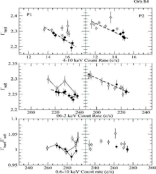 |
Figure 12:
Orbit 84: the
|
| Open with DEXTER | |
In the text
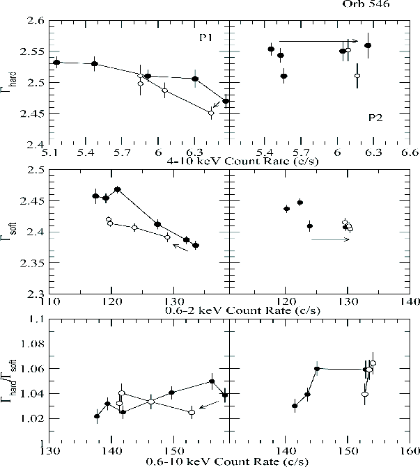 |
Figure 13: Same as Fig. 12, but for the parts "P1'' and "P2" in orbit 546. |
| Open with DEXTER | |
In the text
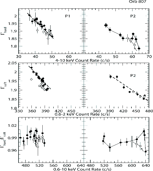 |
Figure 14: Same as Fig. 12, but for the parts "P1'' and "P2'' in orbit 807. |
| Open with DEXTER | |
In the text
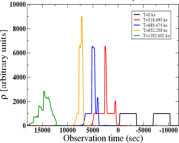 |
Figure 15: Density (in arbitrary units) of the colliding shells at different evolution times (in the jet frame) of the system as seen by a distant observer. The observation time (with arbitrary origin) runs from right to left. The plot shows at what times the observer would "see'' the various structures approaching him with relativistic velocities. |
| Open with DEXTER | |
In the text
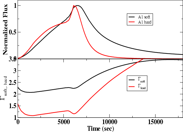 |
Figure 16: Normalized X-ray emission from the model of Fig. 15 in the top panel in the hard (1-10 keV, red curve) and the soft (0.1-1 keV) X-ray band. The bottom panel shows the evolution of the spectral power law indices in the two bands. |
| Open with DEXTER | |
In the text