We present ISO-LWS spectral line observations of the [OI] 63 and 146
A&A 406, 155-164 (2003)
DOI: 10.1051/0004-6361:20030727
P. A. Aannestad 1 - R. J. Emery2
1 - Department of Physics and Astronomy, Arizona State University,
Tempe, AZ 85287-1504, USA
2 -
Space Science Department, Rutherford Appleton Lab, Chilton, Oxon OX11 0QX, UK
Received 21 March 2003 / Accepted 12 May 2003
Abstract
We present ISO-LWS spectral line observations of the [OI] 63 and 146 ![]() m lines,
the [CII] 158
m lines,
the [CII] 158 ![]() m line, and the [NII] 122
m line, and the [NII] 122 ![]() m line at 17 positions in the
HII region S125. We model this emission by a two-dimensional geometrical blister model,
utilizing the parameters derived from our previous modeling of the HII, HI and FIR
dust emission in this source, thereby deriving an interpretation of the region
that takes account of the thermal continuum radiation and the line emission self-
consistently.
We show very good agreement with the observed line emission in
the central region, but in order to fit the spatial profile, it is necessary to
allow for a systematic increase
in the gas temperature along the PDR boundary with decreasing distance from the ionizing
star. This would not be predicted
by PDR models, hence we suggest that the size distribution of small grains responsible for
the photoelectric heating may be changing along the boundary, depending on the
distance from the star. The model shows that the HII region, the PDR region, as well as H2molecular region all make contributions to the emission observed in these fine structure
lines and that accurate modeling of the PDR region needs to include the radiation coupling
between the ionized
region and the neutral molecular cloud. Comparison with values derived from one-dimensional,
constant density slab models shows the present blister modeling giving higher G0 values for the radiation field at the PDR boundary.
m line at 17 positions in the
HII region S125. We model this emission by a two-dimensional geometrical blister model,
utilizing the parameters derived from our previous modeling of the HII, HI and FIR
dust emission in this source, thereby deriving an interpretation of the region
that takes account of the thermal continuum radiation and the line emission self-
consistently.
We show very good agreement with the observed line emission in
the central region, but in order to fit the spatial profile, it is necessary to
allow for a systematic increase
in the gas temperature along the PDR boundary with decreasing distance from the ionizing
star. This would not be predicted
by PDR models, hence we suggest that the size distribution of small grains responsible for
the photoelectric heating may be changing along the boundary, depending on the
distance from the star. The model shows that the HII region, the PDR region, as well as H2molecular region all make contributions to the emission observed in these fine structure
lines and that accurate modeling of the PDR region needs to include the radiation coupling
between the ionized
region and the neutral molecular cloud. Comparison with values derived from one-dimensional,
constant density slab models shows the present blister modeling giving higher G0 values for the radiation field at the PDR boundary.
Key words: HII regions - ISM: individual objects: S125- ISM: dust, extinction - infrared: ISM
The HII region S125 (IC 5146) is an ionized region formed on the near side
of a molecular cloud by the single B0.5 star
![]() 3474,
and showing nearly
symmetrical emission characteristic of a blister type region viewed face-on.
The distance to S125 is taken as 960 pc (Crampton & Fisher 1974); a slightly
larger distance is recently given by Herbig & Dahm (2002) (cf. Sect. 6).
Roger & Irwin (1982, RI hereafter) presented a model to reproduce the emission
profiles of both the radio continuum from the HII region and the HI 21 cm emission from
the photodissociation region (PDR). Using in addition ISO LWS
continuum observations from two perpendicular scans
across the center of the nebula, Aannestad & Emery (2001, herafter AE)
modeled the continuum emission of the region with both the RI model and an axisymmetric blister model.
Assuming enhanced far-infrared (FIR) emission properties for the dust compared to
typical interstellar silicate-graphite dust, the models could fairly well
account for the central FIR emission. However, AE found it
necessary to account for an additional
FIR continuum component in a roughly symmetrical region around and at the
periphery of the HII region. This component appeared to contribute up to about 50% of the observed 45-200
3474,
and showing nearly
symmetrical emission characteristic of a blister type region viewed face-on.
The distance to S125 is taken as 960 pc (Crampton & Fisher 1974); a slightly
larger distance is recently given by Herbig & Dahm (2002) (cf. Sect. 6).
Roger & Irwin (1982, RI hereafter) presented a model to reproduce the emission
profiles of both the radio continuum from the HII region and the HI 21 cm emission from
the photodissociation region (PDR). Using in addition ISO LWS
continuum observations from two perpendicular scans
across the center of the nebula, Aannestad & Emery (2001, herafter AE)
modeled the continuum emission of the region with both the RI model and an axisymmetric blister model.
Assuming enhanced far-infrared (FIR) emission properties for the dust compared to
typical interstellar silicate-graphite dust, the models could fairly well
account for the central FIR emission. However, AE found it
necessary to account for an additional
FIR continuum component in a roughly symmetrical region around and at the
periphery of the HII region. This component appeared to contribute up to about 50% of the observed 45-200 ![]() m emission, and may represent a distribution
of embedded objects at an early stage of protostellar evolution.
m emission, and may represent a distribution
of embedded objects at an early stage of protostellar evolution.
Here we present the FIR fine structure line observations from the LWS scans and attempt to model the line emission within the constraints of the earlier blister model parameters, as determined from the continuum onservations. Since some of the emission comes from the HII region and some from the PDR and the molecular regions, the modeling is necessary in order to separate the contributions and deduce the individual properties of the regions.
In Sect. 2 we present the line observations, while Sect. 3 summarizes the model properties. Section 4 describes the treatment of the line emission, and the calculations are presented in Sect. 5. Discussion is in Sect. 6 and conclusions are presented in Sect. 7.
The LWS scans are crosswise at 45 degrees with respect to the right ascension
and declination directions and centered on the position RA(2000) =
![]() .
Figure 1 shows the 17 scan positions on an image from the Digitized Sky Survey
(Skyview Virtual Telescope). The scan positions are separated by 3' from center
to center.
The approximately 80'' FWHM beam is also indicated. The ionizing star is
at a position 0.68' West and 0.29' South of the central raster
position.
.
Figure 1 shows the 17 scan positions on an image from the Digitized Sky Survey
(Skyview Virtual Telescope). The scan positions are separated by 3' from center
to center.
The approximately 80'' FWHM beam is also indicated. The ionizing star is
at a position 0.68' West and 0.29' South of the central raster
position.
![\begin{figure}
\par\includegraphics[width=8.8cm,clip]{H4401F1.epsi}
\end{figure}](/articles/aa/full/2003/28/aah4401/img8.gif) |
Figure 1:
Raster scan positions for the LWS beam in a
|
The lines observed are the 63 ![]() m (J=1-2) and 146
m (J=1-2) and 146 ![]() m (J=0-1)
from the 3P ground term of
OI, the 158
m (J=0-1)
from the 3P ground term of
OI, the 158 ![]() m (
J=3/2-1/2) line from the 2P ground term of CII,
and the 122
m (
J=3/2-1/2) line from the 2P ground term of CII,
and the 122 ![]() m (J=2-1) line from the 3P ground term of NII.
All the lines are seen in the central positions, but in the outer positions
only the 63
m (J=2-1) line from the 3P ground term of NII.
All the lines are seen in the central positions, but in the outer positions
only the 63 ![]() m and the 158
m and the 158 ![]() m lines are observed. The ionization
potential for NII is 14.5 eV, so the NII line is formed only within the ionized region.
The observed line strengths are listed for each position in the scans in Table 1,
together with the observed FIR continuum flux from 45 to 200
m lines are observed. The ionization
potential for NII is 14.5 eV, so the NII line is formed only within the ionized region.
The observed line strengths are listed for each position in the scans in Table 1,
together with the observed FIR continuum flux from 45 to 200 ![]() m.
The data were recorded with the mode LWS01 and processed with the standard pipeline.
The spectral scans were imported into the ISAP interactive processing package for averaging
and extracting the observed line parameters. This involved a linear fit across
selected portions of the spectrum on either side of the line that was then used
to remove the underlying continuum. A best fit Gaussian profile was used to obtain the
center wavelength and integrated flux of the line, together with some basic
statistics of the fit. The errors shown in Table 1 are estimates of the uncertainties
taking into account these statistical values together with estimates of systematic effects.
The values entered for the line observations are the intensities S
(erg cm-2 s-1 sr-1) =
m.
The data were recorded with the mode LWS01 and processed with the standard pipeline.
The spectral scans were imported into the ISAP interactive processing package for averaging
and extracting the observed line parameters. This involved a linear fit across
selected portions of the spectrum on either side of the line that was then used
to remove the underlying continuum. A best fit Gaussian profile was used to obtain the
center wavelength and integrated flux of the line, together with some basic
statistics of the fit. The errors shown in Table 1 are estimates of the uncertainties
taking into account these statistical values together with estimates of systematic effects.
The values entered for the line observations are the intensities S
(erg cm-2 s-1 sr-1) =
![]() ,
where F is the observed flux, f is the extended source correction,
and
,
where F is the observed flux, f is the extended source correction,
and
![]() is the effective beamwidth. The quantities f and
is the effective beamwidth. The quantities f and
![]() have been taken from Table 5.10 in the ISO Handbook (Gry et al. 2002). For the 45-200
have been taken from Table 5.10 in the ISO Handbook (Gry et al. 2002). For the 45-200 ![]() m continuum we have entered the values from Table 1 of AE using
m continuum we have entered the values from Table 1 of AE using
![]() sr.
sr.
Much of the theoretical treatment of infrared emission from photodissociated regions
has assumed a one-dimensional slab geometry with a constant density into the cloud,
but with a full treatment of the thermal and chemical structure of the gas
(e.g., Tielens & Hollenbach 1985; Hollenbach et al. 1991; Kaufman et al.
1999). In addition, the external radiation field is treated as a free
parameter, normalized to the general interstellar field.
As a development of this, we model the S125 region as a two-dimensional structure
and allow for an axisymmetric density gradient. Whilst gaining a more representative geometry, it
has been necessary to adopt a more simplified thermal treatment,
and to exclude any chemistry except for a detailed account of the HI/H2 conversion.
The modeled PDR structure arises directly from coupling to the
ionization structure and with the actual radiation field through the HII region,
as well as conforming to the continuation of the axisymmetric density gradient.
The input stellar radiation field is taken from a PHOENIX model atmosphere NLTE calculation
by Aufdenberg (1998, private communication) for a star of effective temperature
30 000 K and has an ionizing photon luminosity of
![]() photons/s.
The resulting blister model properties are summarized below, but the reader is
referred to AE for the details. We emphasize that our basic model for the line data
is the same as the best-fit model found by AE for the continuum observations, with
no changes in the parameters so that it addresses all this data self-consistently.
photons/s.
The resulting blister model properties are summarized below, but the reader is
referred to AE for the details. We emphasize that our basic model for the line data
is the same as the best-fit model found by AE for the continuum observations, with
no changes in the parameters so that it addresses all this data self-consistently.
It is assumed that the HII region and the PDR are formed in the outer parts of
a molecular cloud with an exponential density gradient. From the fits to the HII
continuum emission and to the HI 21 cm line emission profiles,
AE found a scale height of 0.65 pc, and a total density (H+He) of 60 cm-3at the ionizing star. Also, from modeling of the dust continuum emission,
AE found it necessary to require a very low dust/gas mass ratio (![]() 10-6) in the HII
region and a region of radius 0.3 pc devoid of dust and gas surrounding the
star. The PDR region, however, was found to have a normal dust/gas mass ratio
(
10-6) in the HII
region and a region of radius 0.3 pc devoid of dust and gas surrounding the
star. The PDR region, however, was found to have a normal dust/gas mass ratio
(
![]() ,
but with a much enhanced population of very small (50 Å)
dust grains.
,
but with a much enhanced population of very small (50 Å)
dust grains.
Figure 2 shows the blister ionization and dissociation boundaries
in an r, ![]() plane (ionizing star at r=0,
plane (ionizing star at r=0,
![]() outward
along the axis), together with
the observed lines of sight for positions N - Q. It is assumed that we are
viewing this blister face-on. The photo-dissociation HI/H2 boundary is defined
by 2N(H2)/(N(H)+2N(H2)) = 0.5.
Also shown as dashed lines are density
contours, which are vertical to the symmetry axis.
We note that the density profile
in the ionized gas along the symmetry axis is very similar to that given by a
photoevaporative flow profile (Bertoldi & Draine 1996)
with the present geometry showing
a cloud of curvature radius 1.3 pc with an axial distance from the
ionizing source to the ionization front of 0.78 pc. Such flow profiles
have been applied to a range of structure sizes, for example, Sankrit & Hester (2000)
fitting for structures in M16, giving a curvature radius
of 0.065 pc and a distance to the ionization front of 0.16 pc.
outward
along the axis), together with
the observed lines of sight for positions N - Q. It is assumed that we are
viewing this blister face-on. The photo-dissociation HI/H2 boundary is defined
by 2N(H2)/(N(H)+2N(H2)) = 0.5.
Also shown as dashed lines are density
contours, which are vertical to the symmetry axis.
We note that the density profile
in the ionized gas along the symmetry axis is very similar to that given by a
photoevaporative flow profile (Bertoldi & Draine 1996)
with the present geometry showing
a cloud of curvature radius 1.3 pc with an axial distance from the
ionizing source to the ionization front of 0.78 pc. Such flow profiles
have been applied to a range of structure sizes, for example, Sankrit & Hester (2000)
fitting for structures in M16, giving a curvature radius
of 0.065 pc and a distance to the ionization front of 0.16 pc.
![\begin{figure}
\par\includegraphics[width=8.8cm,clip]{H4401F2.vps.epsi}
\end{figure}](/articles/aa/full/2003/28/aah4401/img18.gif) |
Figure 2: Blister ionization boundaries for H0/H+, He0/He+, C+/C++, and the H2/H0 photo-dissociation boundary. The heavy solid line shows the "evacuated'' region around the ionizing star. Also shown are the total density contours for 100, 250, 500, and 1000 cm-3, as well as 4 lines of sight for the positions shown in Fig. 1. |
![\begin{figure}
\par\includegraphics[width=8.8cm,clip]{H4401F3.epsi}
\end{figure}](/articles/aa/full/2003/28/aah4401/img19.gif) |
Figure 3: The absorption cross section for the PDR dust and the dust in the HII region as assumed in the model. The dotted curve (DL dust) shows the absorption for a recent model that includes PAH-type dust (Weingartner & Draine 2001a; Li & Draine 2001). |
Figure 3 shows the absorption cross
section per H atom for this dust with the parameters of the PDR region, i.e.
![]() m,
m,
![]() m, and fractional
abundances of Si and C of (0.5, 0.48) and (0.35, 0.27) locked up in the
(large, very small) grains,
respectively. The ratio RV of selective to total visual extinction is 4.3.
The lower curve is the absorption curve for the dust within the HII region,
where the dust appears to be strongly depleted (cf. AE).
For reference we also show the absorption for the recent carbonaceous-silicate
grain model of Weingartner & Draine (2001a)
for the value
RV = 4.0.
In comparison we note the stronger far-UV absorption in the PDR dust due to the large number
of very small grains, and the much enhanced FIR absorption due to a
combination of optical properties and shape effects. The wavelength dependence
at long wavelengths is approximately
m, and fractional
abundances of Si and C of (0.5, 0.48) and (0.35, 0.27) locked up in the
(large, very small) grains,
respectively. The ratio RV of selective to total visual extinction is 4.3.
The lower curve is the absorption curve for the dust within the HII region,
where the dust appears to be strongly depleted (cf. AE).
For reference we also show the absorption for the recent carbonaceous-silicate
grain model of Weingartner & Draine (2001a)
for the value
RV = 4.0.
In comparison we note the stronger far-UV absorption in the PDR dust due to the large number
of very small grains, and the much enhanced FIR absorption due to a
combination of optical properties and shape effects. The wavelength dependence
at long wavelengths is approximately
![]() ,
which is also assumed
in many of the PDR models referred to earlier. A similar dependence
is observed for the FIR emission in many sources.
,
which is also assumed
in many of the PDR models referred to earlier. A similar dependence
is observed for the FIR emission in many sources.
The far-UV radiation field G0 at the PDR surface for the S125 HII
blister
(in units of
![]() erg cm-2 s-1) ranges from about 60 for
erg cm-2 s-1) ranges from about 60 for
![]() ,
to about 103 for
,
to about 103 for
![]() .
The corresponding range in the surface gas density n0 is about 10-200 cm-3 (at distances r of 3.0 and 0.8 pc, respectively).
PDR slab models show that the surface temperature is primarily determined by
the ratio
G0/n0. In the present analysis this is found to be
fairly constant with a value of 5-6 which, in the calculations of Kaufman
et al. (1999) (cf. their Fig. 1), corresponds to a temperature of
500-1000 K, with the higher values applying to the lower densities.
These values are higher than in earlier work (Hollenbach et al. 1991;
Spaans et al. 1994), where, for our values of G0 and n0,
typically the temperature would be 100-200 K in a surface layer of
visual extinction
.
The corresponding range in the surface gas density n0 is about 10-200 cm-3 (at distances r of 3.0 and 0.8 pc, respectively).
PDR slab models show that the surface temperature is primarily determined by
the ratio
G0/n0. In the present analysis this is found to be
fairly constant with a value of 5-6 which, in the calculations of Kaufman
et al. (1999) (cf. their Fig. 1), corresponds to a temperature of
500-1000 K, with the higher values applying to the lower densities.
These values are higher than in earlier work (Hollenbach et al. 1991;
Spaans et al. 1994), where, for our values of G0 and n0,
typically the temperature would be 100-200 K in a surface layer of
visual extinction
![]() .
The higher temperatures in the
Kaufman et al. models are a consequence of PAH heating, and is therefore
closely tied to the far-UV optical depth.
In the earlier work on S125, AE
assumed a simple dependence of the gas temperature on the average
dust temperature and on the optical depth at 0.1
.
The higher temperatures in the
Kaufman et al. models are a consequence of PAH heating, and is therefore
closely tied to the far-UV optical depth.
In the earlier work on S125, AE
assumed a simple dependence of the gas temperature on the average
dust temperature and on the optical depth at 0.1 ![]() m, and took the PDR boundary temperature to be 500 K, independent of distance from the star.
We assume the same temperature structure here, but will also (cf. Sect. 5) consider
possible variations from this.
m, and took the PDR boundary temperature to be 500 K, independent of distance from the star.
We assume the same temperature structure here, but will also (cf. Sect. 5) consider
possible variations from this.
Figure 4 shows the PDR gas temperature as a function of the visual extinction for
some of the lines of sight (cf. Fig. 2). The upper
panel is for the assumption of a constant boundary temperature independent
of the angle ![]() ,
and all the lines of sight fall between the two
curves given for positions N and R. The lower panel shows the temperature
variation for a boundary temperature that varies with the angle
,
and all the lines of sight fall between the two
curves given for positions N and R. The lower panel shows the temperature
variation for a boundary temperature that varies with the angle ![]() in
the way indicated that better satisfies the observed spatial profile of the
fine-structure lines (Sect. 5).
in
the way indicated that better satisfies the observed spatial profile of the
fine-structure lines (Sect. 5).
In Table 2 we summarize the main properties for the blister model. Note that
some properties are limited by how far into the molecular cloud the
calculations are carried. Also, the listed neutral masses and total luminosity does not include
any contrubution from the additional FIR component required to explain the
observed luminosity.
In the PDR region, the collision partners are electrons, H and He atoms, and H2 molecules. For the electron collision strengths, we have fit the
values given by Bell et al. (1998) for
T = 50 - 3000 K by Chebyshev
polynomials. The electron density in the PDR region is set equal to the C+ density. The H and He collision strengths are from the Péquignot
(1990) expressions with corrections as
in Péquignot (1996). The corresponding de-excitation rates are
close to earlier values (Tielens & Hollenbach 1985), except
for the
![]() transition, where the new rates are
an order of magnitude smaller.
For the molecular excitation we use the rate
coefficients for para- and ortho- H2 calculated by Jaquet et al.
(1992) for the temperature range 20-1500 K. We assume the
thermal value of 1:3 for the para:ortho abundance ratio. Since the
excitation rates are very similar for the two species, the actual value
of this ratio is not important here. The H2 collision rates are
substantially larger than the H collision rates, except for the
transition, where the new rates are
an order of magnitude smaller.
For the molecular excitation we use the rate
coefficients for para- and ortho- H2 calculated by Jaquet et al.
(1992) for the temperature range 20-1500 K. We assume the
thermal value of 1:3 for the para:ortho abundance ratio. Since the
excitation rates are very similar for the two species, the actual value
of this ratio is not important here. The H2 collision rates are
substantially larger than the H collision rates, except for the
![]() transition, where rates are 1-2 orders of
magnitude smaller for the PDR temperatures.
transition, where rates are 1-2 orders of
magnitude smaller for the PDR temperatures.
The blister has an exponential density increase into the molecular cloud,
but our calculations are stopped when either: 1) a 10 ![]() m dust optical depth from
the central star
m dust optical depth from
the central star
![]() 0.5, or 2) a distance is reached of 30 scale heights from the central star.
For S125 this corresponds to visual extinctions
0.5, or 2) a distance is reached of 30 scale heights from the central star.
For S125 this corresponds to visual extinctions
![]() .
The calculation encompasses the molecular cloud "surface layer'' where the observed fine-structure
lines are formed. Further into the cloud, in addition to the temperature
becoming too low for excitation, C+ and O are converted into C
and/or CO, and may be additionally depleted onto the dust grains.
The hydrogen nucleon column densities in these calculations are therefore limited to
.
The calculation encompasses the molecular cloud "surface layer'' where the observed fine-structure
lines are formed. Further into the cloud, in addition to the temperature
becoming too low for excitation, C+ and O are converted into C
and/or CO, and may be additionally depleted onto the dust grains.
The hydrogen nucleon column densities in these calculations are therefore limited to
![]() cm-2. This means, however, that both the OI 63
cm-2. This means, however, that both the OI 63 ![]() m and the C+ 158
m and the C+ 158 ![]() m lines become optically thick for all the observed lines of
sight. Typically, when the calculations are stopped,
m lines become optically thick for all the observed lines of
sight. Typically, when the calculations are stopped,
![]() ,
and
,
and
![]() .
The [OI] 146
.
The [OI] 146 ![]() m
line, however, is optically thin, even going through a region with a very slight negative optical depth
for these PDR conditions.
m
line, however, is optically thin, even going through a region with a very slight negative optical depth
for these PDR conditions.
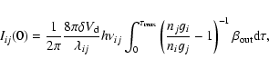
For a given line of sight, the intensity for a line of wavelength
![]() is calculated in the semi-infinite slab approximation:
is calculated in the semi-infinite slab approximation:
To illustrate optical depth effects,
Fig. 5 shows how the line ratios [OI] 63 ![]() m/146
m/146 ![]() m and [OI]63
m and [OI]63 ![]() m/
[CII]158
m/
[CII]158 ![]() m vary with density and temperature for optical depths in the
63
m vary with density and temperature for optical depths in the
63 ![]() m line of 0.01, 1.0 and 5.0. The optical depth
m line of 0.01, 1.0 and 5.0. The optical depth
![]() is the outward optical depth in a uniform, semi-infinite slab. For this purpose,
only excitation by atomic hydrogen has been included. In the low density limit,
the OI 63
is the outward optical depth in a uniform, semi-infinite slab. For this purpose,
only excitation by atomic hydrogen has been included. In the low density limit,
the OI 63 ![]() m/146
m/146 ![]() m line ratio is independent of optical depth
with a value of 17 and 45 for T = 500 K and 100 K, respectively.
For the moderate densities considered here, the ratio decreases to 13 and 40,
respectively, as the 63
m line ratio is independent of optical depth
with a value of 17 and 45 for T = 500 K and 100 K, respectively.
For the moderate densities considered here, the ratio decreases to 13 and 40,
respectively, as the 63 ![]() m line optical depth increases from 0 to 10.
Note that only in the optically thin
limit (upper panel) is the [OI]63
m line optical depth increases from 0 to 10.
Note that only in the optically thin
limit (upper panel) is the [OI]63 ![]() m/[CII]158
m/[CII]158 ![]() m ratio proportional to
the O/C abundance ratio (a value of 2 is assumed in these figures).
We see that the optical
depth strongly affects the line ratios for high density - low temperature
conditions, while the effects for low density - low temperature conditions
are quite small. However, even for relatively low densities as considered here,
assuming optically thin conditions leads to overestimates of either temperature
and/or density.
m ratio proportional to
the O/C abundance ratio (a value of 2 is assumed in these figures).
We see that the optical
depth strongly affects the line ratios for high density - low temperature
conditions, while the effects for low density - low temperature conditions
are quite small. However, even for relatively low densities as considered here,
assuming optically thin conditions leads to overestimates of either temperature
and/or density.
The contribution to the [OI] and [CII] line intensities from collisional excitation by H2 is
substantial in our calculations. In the central positions, it provides ![]() 1/3 of the total
intensity, while in the outer positions it contributes
1/3 of the total
intensity, while in the outer positions it contributes ![]() 2/3 of the line intensities.
Also, the contribution by the HII region is large for the central positions,
varying from 10-20% for the [OI] 63
2/3 of the line intensities.
Also, the contribution by the HII region is large for the central positions,
varying from 10-20% for the [OI] 63 ![]() m, 146
m, 146 ![]() m lines to 40% for the [CII] 158
m lines to 40% for the [CII] 158 ![]() m line. Figure 6 shows the line emissivities (erg cm-3 s-1) along the two
lines of sight for positions N and P. The temperature structure is that of the lower panel
in Fig. 4. Note that the positive direction
is into the blister, and opposite to the abscissa in Fig. 2. The HII/PDR boundary is at 0.75 pc,
-0.21 pc, and the HI/H2 transitions is at 1.7 pc, 1.4 pc for the N, P lines of sight,
respectively (cf. Fig. 2). For clarity, the
values for the [CII] 158
m line. Figure 6 shows the line emissivities (erg cm-3 s-1) along the two
lines of sight for positions N and P. The temperature structure is that of the lower panel
in Fig. 4. Note that the positive direction
is into the blister, and opposite to the abscissa in Fig. 2. The HII/PDR boundary is at 0.75 pc,
-0.21 pc, and the HI/H2 transitions is at 1.7 pc, 1.4 pc for the N, P lines of sight,
respectively (cf. Fig. 2). For clarity, the
values for the [CII] 158 ![]() m line has been decreased by 2 and 3 orders of magnitude for
positions N and P, respectively. It is apparent that accounting for emission in both ionized
gas and in fully molecular gas is important for understanding PDR emission in these
fine-structure lines.
m line has been decreased by 2 and 3 orders of magnitude for
positions N and P, respectively. It is apparent that accounting for emission in both ionized
gas and in fully molecular gas is important for understanding PDR emission in these
fine-structure lines.
Figures 7-9 show the calculated line intensities for the OI and CII lines along the ISO scans A - I and J - R together with the observed values. The upper solid curve in each panel is the total line intensity, while the lower curve is for the contribution by the HII region only. The line intensities are matched very well in the center position, but points immediately around the center (M and O) are higher in intensity than calculated by up to a factor of 2.8. This seems to reflect the same result as found by AE, i.e. additional emission is present symmetrically placed around the center. However, contrary to the observed dust continuum emission, the observed line emission falls below the model emission in the other positions further away from the center.
The most direct interpretation of this is that the gas temperature at the boundary
decreases with distance from the central star, rather than staying approximately
constant as predicted by the theory of PDR heating and cooling (approx. constant
G0/n0). To parameterize this in the present model, we
have taken the boundary temperature to be an increasing function of the angle ![]() for the closed portion of the
for the closed portion of the ![]() plane.
The dashed lines in Figs. 7-9 show the resulting model
intensities if
plane.
The dashed lines in Figs. 7-9 show the resulting model
intensities if
![]() K for
80
K for
80
![]() ,
,
![]() K for
K for
![]() ,
,
![]() K for
K for
![]() .
The temperature structure in this case is
shown in the lower panel of Fig. 4. Possible physical reasons for a
variation of the boundary temperature are discussed in Sect. 6.
.
The temperature structure in this case is
shown in the lower panel of Fig. 4. Possible physical reasons for a
variation of the boundary temperature are discussed in Sect. 6.
![\begin{figure}
\par\includegraphics[width=8.8cm,clip]{H4401F7.epsi}
\end{figure}](/articles/aa/full/2003/28/aah4401/img61.gif) |
Figure 7:
Observed and calculated line intensities (erg cm-2 s-1 sr-1) for the [OI] 63 |
![\begin{figure}
\par\includegraphics[width=8.8cm,clip]{H4401F8.epsi}
\end{figure}](/articles/aa/full/2003/28/aah4401/img62.gif) |
Figure 8:
Observed and calculated line intensities for the [OI] 146 |
![\begin{figure}
\par\includegraphics[width=8.8cm,clip]{H4401F9.epsi}
\end{figure}](/articles/aa/full/2003/28/aah4401/img63.gif) |
Figure 9:
Observed and calculated line intensities for the [CII] 158 |
The observed intensities of the [NII] 122 ![]() m line for the central positions
(Table 1) are
m line for the central positions
(Table 1) are
![]() erg cm-2 s-1 sr-1, while our
calculated values are
erg cm-2 s-1 sr-1, while our
calculated values are
![]() erg cm-2 s-1 sr-1.
As a comparison with more generalized models, we have run the one-dimensional
photoionization code CLOUDY (version C94.00, Ferland 2000)
for a constant density ionized shell that has the same emission measure
(about 8000 cm-6 pc)
as observed and is subject to the same ionizing luminosity
(9.3
erg cm-2 s-1 sr-1.
As a comparison with more generalized models, we have run the one-dimensional
photoionization code CLOUDY (version C94.00, Ferland 2000)
for a constant density ionized shell that has the same emission measure
(about 8000 cm-6 pc)
as observed and is subject to the same ionizing luminosity
(9.3
![]() erg s-1,
Kurucz 30 000 K model atmosphere) as in our calculations. With an inner radius of the shell
set to 0.3 pc (our evacuated region around the star), and an average constant hydrogen
density of 130 cm-3 (in our blister model the density in the HII region ranges from 85 cm-3 at 0.3 pc to 180 cm-3 at the HII boundary),
the outer radius of the shell (0.8 pc) and the H+ column density (
erg s-1,
Kurucz 30 000 K model atmosphere) as in our calculations. With an inner radius of the shell
set to 0.3 pc (our evacuated region around the star), and an average constant hydrogen
density of 130 cm-3 (in our blister model the density in the HII region ranges from 85 cm-3 at 0.3 pc to 180 cm-3 at the HII boundary),
the outer radius of the shell (0.8 pc) and the H+ column density (
![]() cm-2) agree well with our blister parameters along the central line of sight
(
cm-2) agree well with our blister parameters along the central line of sight
(
![]() ).
For the predicted [NII] 122
).
For the predicted [NII] 122 ![]() m luminosity of the S125 region, the CLOUDY value
is also consistent with our calculation, and again shows a higher value
compared with the observation, taking an integrated value and a smooth distribution
between pointing positions.
It may be that the nitrogen abundance in S125 is subsolar by about about a factor of two,
similar to the abundance in M16 (Sankrit & Hester 2000). Alternatively,
it may indicate too high an ionizing radiation field from the PHOENIX model atmosphere,
which does not include the effects of a stellar wind.
m luminosity of the S125 region, the CLOUDY value
is also consistent with our calculation, and again shows a higher value
compared with the observation, taking an integrated value and a smooth distribution
between pointing positions.
It may be that the nitrogen abundance in S125 is subsolar by about about a factor of two,
similar to the abundance in M16 (Sankrit & Hester 2000). Alternatively,
it may indicate too high an ionizing radiation field from the PHOENIX model atmosphere,
which does not include the effects of a stellar wind.
The calculated values for the [NII] 205 ![]() m line from our model in
the central position is
m line from our model in
the central position is
![]() erg cm-2 s-1 sr-1, or
about 1/3 of the 122
erg cm-2 s-1 sr-1, or
about 1/3 of the 122 ![]() m line lintensity. For the other lines also formed entirely in
the HII region, we predict the following intensity values for the central
position: I([OIII]88
m line lintensity. For the other lines also formed entirely in
the HII region, we predict the following intensity values for the central
position: I([OIII]88
![]() erg cm-2 s-1 sr-1,
I([OIII]52
erg cm-2 s-1 sr-1,
I([OIII]52
![]() erg cm-2 s-1 sr-1,
and I([NIII]57
erg cm-2 s-1 sr-1,
and I([NIII]57
![]() erg cm-2 s-1 sr-1.
erg cm-2 s-1 sr-1.
The observations also show that the FIR line emission displays the same "excess
emission'' as the continuum emission in a roughly symmetric region around and at the
periphery of the HII region. For example, in order to account
for the LWS continuum emission within the beam at position O, it is required that all the
UV stellar flux in this direction is absorbed completely and only by the dust and re-emitted
only in the FIR. This is not physically reasonable.
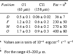
We have earlier characterized this emission by subtracting
our model flux from the observed flux (AE, e.g. Fig. 15). In Table 2 we have similarly
subtracted our model line fluxes from the observed fluxes at the symmetrically placed
positions D, F, M, and O for the [OI] 63 ![]() m and [CII] 158
m and [CII] 158 ![]() m lines. We have also listed
an approximate value for the FIR continuum emission for this "excess'' component by
using the "excess'' in the 45-200
m lines. We have also listed
an approximate value for the FIR continuum emission for this "excess'' component by
using the "excess'' in the 45-200 ![]() m range, but increased it by 20% to take account of emission
below 45
m range, but increased it by 20% to take account of emission
below 45 ![]() m.
m.
Although the additional component values listed in Table 2 have additional uncertainty
due to the subtraction, some further tentative conclusions can be drawn.
Assuming PDR conditions, according to the
calculations by Kaufman et al.
(1999, their Figs. 3-4), the values for the line ratio in Table 2
imply
![]() and
and
![]() cm-3. The intensity ratios ([OI]63
cm-3. The intensity ratios ([OI]63 ![]() m + [CII]158
m + [CII]158 ![]() m)/FIR from
Table 2, however, are very similar to the general values, but are also consistent with a high-density
component,
m)/FIR from
Table 2, however, are very similar to the general values, but are also consistent with a high-density
component,
![]() cm-3 (cf. Kaufman et al. 1999, their Fig. 6).
cm-3 (cf. Kaufman et al. 1999, their Fig. 6).
We can compare the G0 and n values given by our model with those derived from the
observations together with the PDR models of Kaufman et al. (1999),
recognizing thet these typically give more than one possible solution in the n,
G0 plane.
In the present case, solutions can give a high G0 value
coupled with a low n value, or conversely
a low G0 value with a high n. To correct for the emission component from the
HII region, we subtract our calculated contributions from
the HII region alone from the observed intensities. The best determined values in the present observations are the
intensity levels of the [CII] 158 ![]() m line and the line ratios [OI]63
m line and the line ratios [OI]63 ![]() m/[CII]158
m/[CII]158 ![]() m.
Using these with the PDR models leads to two possible solutions for most of the observed
positions. However, in all cases our blister values for G0, n fall in the same
part of the diagram with high G0 and low n. Although the observed
[OI]146
m.
Using these with the PDR models leads to two possible solutions for most of the observed
positions. However, in all cases our blister values for G0, n fall in the same
part of the diagram with high G0 and low n. Although the observed
[OI]146 ![]() m/[OI]63
m/[OI]63 ![]() m line ratios are also available, they have significantly
greater uncertainty. However, their use also points to the same (high G0 with low n)
part of the diagram.
For example, for the central position (E,N) the observed values corrected for HII emission
are: I([CII]158
m line ratios are also available, they have significantly
greater uncertainty. However, their use also points to the same (high G0 with low n)
part of the diagram.
For example, for the central position (E,N) the observed values corrected for HII emission
are: I([CII]158
![]() erg cm-2 s-1 sr-1,
I([OI]63
erg cm-2 s-1 sr-1,
I([OI]63 ![]() m)/I([CII]158
m)/I([CII]158 ![]() m) = 0.9, (I([OI]63
m) = 0.9, (I([OI]63 ![]() m)+I([CII]158
m)+I([CII]158 ![]() m))/
m))/
![]() ,
and I([OI]146
,
and I([OI]146 ![]() m)/I([OI]63
m)/I([OI]63 ![]() m) = 0.085.
Using these values, the PDR models imply
G0 = 100 - 500 and
m) = 0.085.
Using these values, the PDR models imply
G0 = 100 - 500 and
![]() cm-3. In comparison, the values in the
present blister model at the PDR boundary for the central position are
G0 = 900 and n = 180 cm-3.
These parameters were set independently of the FIR line measurements, but ,
as shown, give line intensities in very good agreement
with the observed values. In general for S125, constant density slab models tend to underestimate
the radiation field at the HII/PDR boundary.
cm-3. In comparison, the values in the
present blister model at the PDR boundary for the central position are
G0 = 900 and n = 180 cm-3.
These parameters were set independently of the FIR line measurements, but ,
as shown, give line intensities in very good agreement
with the observed values. In general for S125, constant density slab models tend to underestimate
the radiation field at the HII/PDR boundary.
Kaufman et al. (1999) use an approximation to the FIR dust continuum of
![]() G0 erg cm-2 s-1 sr-1, which includes
a factor of 2 for radiation absorbed outside the wavelength interval that defines G0.
From the blister model that provides a good match to the observations
we find
G0 erg cm-2 s-1 sr-1, which includes
a factor of 2 for radiation absorbed outside the wavelength interval that defines G0.
From the blister model that provides a good match to the observations
we find
![]() G0 erg cm-2 s-1 sr-1.
A lower rate of dust emission is caused by a lower bolometric correction (1.35) and
allowing for absorption of radiation by H2 (photodissociation). The photoelectric heating
efficiency is determined by the ratio (I([OI]63
G0 erg cm-2 s-1 sr-1.
A lower rate of dust emission is caused by a lower bolometric correction (1.35) and
allowing for absorption of radiation by H2 (photodissociation). The photoelectric heating
efficiency is determined by the ratio (I([OI]63 ![]() m) + I([CII]158
m) + I([CII]158 ![]() m))/
m))/
![]() .
An efficiency of
.
An efficiency of ![]() 10-2 (Table 1) corresponds to a
value
10-2 (Table 1) corresponds to a
value
![]() K1/2 cm3 in theories of photoelectric
emission (Bakes & Tielens 1994; Weingartner & Draine 2001b). For the line of
sight in position N,
K1/2 cm3 in theories of photoelectric
emission (Bakes & Tielens 1994; Weingartner & Draine 2001b). For the line of
sight in position N,
![]() varies from
varies from
![]() at the PDR
boundary to
at the PDR
boundary to
![]() K1/2 cm3 when
K1/2 cm3 when
![]() .
The present
observations and modeling parameters therefore give support to these descriptions of
photoelectric heating.
.
The present
observations and modeling parameters therefore give support to these descriptions of
photoelectric heating.
Only collisional excitation of the fine structure levels have been included in our modeling.
Addressing only the [OI] line ratios,
Keenan et al. (1994) note that the
![]() and
and
![]() levels in OI can be populated by cascades from higher states that
have been populated from the
levels in OI can be populated by cascades from higher states that
have been populated from the
![]() level through absorption of UV radiation. If we just include their effective rates of
level through absorption of UV radiation. If we just include their effective rates of
![]() s-1 for indirect excitation of
s-1 for indirect excitation of
![]() from
from
![]() and
and
![]() s-1 for indirect excitation of
s-1 for indirect excitation of
![]() from
from
![]() ,
where Gis the UV radiation field normalized by Keenan et al. to the Gondhalekar et al. (1980)
interstellar radiation field (G=1 corresponds to a flux of
,
where Gis the UV radiation field normalized by Keenan et al. to the Gondhalekar et al. (1980)
interstellar radiation field (G=1 corresponds to a flux of
![]() erg cm-2 s-1), the 63
erg cm-2 s-1), the 63 ![]() m and 146
m and 146 ![]() m model line intensities for our
lines of sight are then generally too high compared to the observations by factors
m model line intensities for our
lines of sight are then generally too high compared to the observations by factors ![]() 1.5. However, the rate coefficients do depend on accurate values for the transition oscillator
strengths and on the actual shape of the UV radiation field. Also, the model line fluxes could
be lowered by using a lower gas phase oxygen abundance than assumed here,
if the abundance is subsolar and/or if some of the oxygen is locked up in the dust.
1.5. However, the rate coefficients do depend on accurate values for the transition oscillator
strengths and on the actual shape of the UV radiation field. Also, the model line fluxes could
be lowered by using a lower gas phase oxygen abundance than assumed here,
if the abundance is subsolar and/or if some of the oxygen is locked up in the dust.
Since chemistry has not been included in our modeling, it should be noted that this limits
the calculations to the region where C is C+and O is OI. However, the PDR slab models show that this corresponds to
![]() for a 30 000 K
radiation field (Spaans et al. 1994), which encompasses our model region since this is
generally where our calculation
stops. Also, at these depths into the cloud, the gas temperature is becoming significantly less than
the excitation temperature of the lines, and the contribution to the line intensity is small.
for a 30 000 K
radiation field (Spaans et al. 1994), which encompasses our model region since this is
generally where our calculation
stops. Also, at these depths into the cloud, the gas temperature is becoming significantly less than
the excitation temperature of the lines, and the contribution to the line intensity is small.
One main uncertainty in these calculations is the simplified treatment of line radiative transfer. However, it is difficult to judge the accuracy of the escape probability method, here used in the semi-infinite slab, one-dimensional approximation. Two-dimensional methods, such as those presented by Hogerheijde & van der Tak (2000) and by van Noort et al. (2002) would be very useful for blister calculations. Also, we have not allowed for any clumpiness of the gas in S125. While our modeling does not rule out clumpiness, it shows that, for this source at least, results consistent with the observations are obtained with a smooth density gradient from the HII region into the molecular cloud. It does, however, as discussed above, require that the gas temperature at the blister PDR boundary increases systematically with decreasing distance to the ionizing star.
In a recent paper, Herbig & Dahm (2002) have done visual and near-ir photometry of the cluster members in IC5146. They suggest a revised distance to the cluster of 1.2 kpc, but with an uncertainty of at least 0.2 kpc. A larger distance than our adopted one (960 pc) will primarily affect the physical scale of the emission region. Thus the off center beam positions will correspond to conditions slightly further away from the central star in our model nebula, with corresponding lower calculated continuum and line emission for the raster positions. This would make the postulated "excess emission'' a slightly greater fraction of the total. In addition, the line profiles (Figs. 7-9) would become narrower, which would reduce, but not eliminate, the required change in the PDR boundary temperature (Sect. 5).
It is clear from the emission mapping given by the blister model that the line emission shows an "excess'' in a region immediately surrounding the central position, similar to that shown by the dust continuum emission. This appears to be from a higher density ( n > 104 cm-3) region that may be heated by embedded sources to give emission components that are in addition to those accounted for by the blister model with a central ionizing star.
The present modeling gives the emission contributions from the various regions of S125 that together
make up the observed value. From this, for example, the contribution to the [CII] and the [OI] line
intensities emanating from the HII region are found to be ![]() 40% and
40% and ![]() 20%, respectively,
showing that this should be taken into account in PDR modeling.
20%, respectively,
showing that this should be taken into account in PDR modeling.
For interpreting the [OI] 63 ![]() m and [CII] 158
m and [CII] 158 ![]() m lines,
these are found to be moderately optically
thick in the blister, whilst
the [OI] 146
m lines,
these are found to be moderately optically
thick in the blister, whilst
the [OI] 146 ![]() m line is optically thin with a region of slight negative optical depth. For
the relatively low density conditions derived here for S125, however, this shows that the line intensities
are affected by less than a factor of two.
m line is optically thin with a region of slight negative optical depth. For
the relatively low density conditions derived here for S125, however, this shows that the line intensities
are affected by less than a factor of two.
Comparison with an equivalent analysis, using a one-dimensional constant density PDR slab model, shows that our blister model implies a higher value for the incident radiation at the PDR boundary.
Acknowledgements
We would like to thank the referee, Dr. G. Sandell, for helpful comments in the referee phase. For the early part of this investigation we are indebted to the NATO Collaborative Research Program under grant No. 960326.
![\begin{figure}
\par\includegraphics[width=8.8cm,clip]{H4401F4.epsi}
\end{figure}](/articles/aa/full/2003/28/aah4401/img33.gif)
![\begin{table}
\par
\begin{displaymath}
\begin{array}{p{0.5\linewidth}l}
\hline\h...
...m[$^{{\rm b}}$ ] To the limits of the calculation.
\par\end{list}\par\end{table}](/articles/aa/full/2003/28/aah4401/img34.gif)
![\begin{figure}
\par\includegraphics[width=8.8cm,clip]{H4401F5.epsi}
\end{figure}](/articles/aa/full/2003/28/aah4401/img51.gif)
![\begin{figure}
\par\includegraphics[width=8.8cm,clip]{H4401F6.epsi}
\end{figure}](/articles/aa/full/2003/28/aah4401/img53.gif)