A&A 382, 624-638 (2002)
DOI: 10.1051/0004-6361:20011646
D. Teyssier - P. Hennebelle - M. Pérault
Laboratoire de radioastronomie millimétrique, URA 336 du CNRS, École normale supérieure et Observatoire de Paris, 24 rue Lhomond, 75231 Paris Cedex 05, France
Received 29 December 2000 / Accepted 13 November 2001
Abstract
We present follow-up observations of the mid-Infrared dark clouds selected from the ISOGAL inner Galaxy sample. On-the-fly maps of 13CO, C18O and the 1.2 mm continuum emission were conducted at the IRAM 30-m telescope, showing spectacular correlation with the mid-IR absorption. The dark clouds are distributed as far as the prominent molecular ring at a distance of 3 to 7 kpc from the Sun. The clouds exhibit shapes ranging from globules to thin filaments down to
![]() 1 pc in size. The on-the-fly images obtained in 13CO and C18O confirmed that the cores are dense, compact molecular emitters, significantly more massive than local dark clouds (more than 1000
1 pc in size. The on-the-fly images obtained in 13CO and C18O confirmed that the cores are dense, compact molecular emitters, significantly more massive than local dark clouds (more than 1000 ![]() )
and lie within low activity Giant Molecular Clouds (GMC's). Ratios of the emission in the J=(2-1) and (1-0) transitions of 13CO and C18O show a remarkable uniformity within each cloud, with a significant portion of the sample represented well by a ratio of
)
and lie within low activity Giant Molecular Clouds (GMC's). Ratios of the emission in the J=(2-1) and (1-0) transitions of 13CO and C18O show a remarkable uniformity within each cloud, with a significant portion of the sample represented well by a ratio of
![]() .
Preliminary analysis of temperature and density measurements reveals that most of the cores have densities above 105 cm-3 and temperatures between 8 and 25 K, these latter clouds being associated with young embedded stars. Despite the high extinction inferred from mid-IR (
.
Preliminary analysis of temperature and density measurements reveals that most of the cores have densities above 105 cm-3 and temperatures between 8 and 25 K, these latter clouds being associated with young embedded stars. Despite the high extinction inferred from mid-IR (
![]() ,
Hennebelle et al. 2001), the molecular lines are surprisingly weak, indicating likely depletion onto cold grains.
,
Hennebelle et al. 2001), the molecular lines are surprisingly weak, indicating likely depletion onto cold grains.
Key words: ISM: clouds - molecules - structure - radio continuum: ISM - radio lines: ISM
Galactic dark clouds observed in the mid-Infrared were first surveyed by ISO
(Pérault et al. 1996), and turn out to be the highly condensed parts of Giant Molecular Clouds (GMC's) kiloparsecs away from the Sun.
The ISOGAL survey imaged ![]() 10% of the inner Galactic ridge, mostly towards relatively quiescent areas, in broad filters around 7 and 15
10% of the inner Galactic ridge, mostly towards relatively quiescent areas, in broad filters around 7 and 15 ![]() m (Omont et al. 1999). A systematic analysis of the ISOGAL plates (Hennebelle et al. 2001, hereafter Paper I) allowed extraction of a catalogue of about 450 objects, most of them located in the inner Galaxy. The features are associated with GMC's lying between 3 and 7 kpc from us. In Paper I, we derived opacities at 15
m (Omont et al. 1999). A systematic analysis of the ISOGAL plates (Hennebelle et al. 2001, hereafter Paper I) allowed extraction of a catalogue of about 450 objects, most of them located in the inner Galaxy. The features are associated with GMC's lying between 3 and 7 kpc from us. In Paper I, we derived opacities at 15 ![]() m in the range 1 to 4 for a few selected objects, leading to column densities of the order of 1023 cm-2.
m in the range 1 to 4 for a few selected objects, leading to column densities of the order of 1023 cm-2.
Similar findings have been reported by Egan et al. (1998) from the MSX (Midcourse Space Experiment) survey of the whole Galactic plane. They counted about 2000 IR dark clouds (IRDC's) located in the same distance range as the ISOGAL clouds and estimated extinctions at 8 ![]() m in excess of 2. Detections of few clouds at millimetre wavelengths (Carey et al. 1998) confirmed that these objects are dense (
m in excess of 2. Detections of few clouds at millimetre wavelengths (Carey et al. 1998) confirmed that these objects are dense (
![]() cm-3) and cold (T < 20 K). The authors conclude that these clouds are pre-protostellar cores where no sign of star-formation has been detected so far. This analysis was recently refined using continuum detection at 850 and 450
cm-3) and cold (T < 20 K). The authors conclude that these clouds are pre-protostellar cores where no sign of star-formation has been detected so far. This analysis was recently refined using continuum detection at 850 and 450 ![]() m (Carey et al. 2000). The relatively high masses inferred from the submillimetre observations suggest a significant potential for stellar formation in these cores.
m (Carey et al. 2000). The relatively high masses inferred from the submillimetre observations suggest a significant potential for stellar formation in these cores.
In the present paper we analyse spectroscopic and continuum follow-up observations of the ISOGAL dark features, conducted at the IRAM 30-m telescope. A sample of 13 objects has been mapped in several molecular tracers. A few characteristic physical parameters are inferred. The spatial resolution of these observations (11
![]() at 1.3 mm) opens the way to the analysis of the gas associated with the dense dust revealed by the mid-IR absorption at an intermediate spatial scale. Our main purpose is to compare the properties of our objects to those of the well-known local dark clouds. A subsequent study will provide an extensive analysis of temperature and density measurements and better assess the physico-chemical processes at work in the clouds (Teyssier et al. 2001b).
Section 2 presents the observational conditions and strategy.
In Sect. 3 we describe the correlation between the millimetre emission and the IR absorption data. The nature of the different objects is assessed and a detailed spatial and spectral analysis is introduced. Section 4 gives the physical properties of the clouds and their relation to the mid-IR opacities estimated in Paper I. Section 5 summarises our conclusions.
at 1.3 mm) opens the way to the analysis of the gas associated with the dense dust revealed by the mid-IR absorption at an intermediate spatial scale. Our main purpose is to compare the properties of our objects to those of the well-known local dark clouds. A subsequent study will provide an extensive analysis of temperature and density measurements and better assess the physico-chemical processes at work in the clouds (Teyssier et al. 2001b).
Section 2 presents the observational conditions and strategy.
In Sect. 3 we describe the correlation between the millimetre emission and the IR absorption data. The nature of the different objects is assessed and a detailed spatial and spectral analysis is introduced. Section 4 gives the physical properties of the clouds and their relation to the mid-IR opacities estimated in Paper I. Section 5 summarises our conclusions.
Observations of 13 IR dark clouds were conducted at the IRAM 30-m telescope between July 1998 and August 1999.
Two summer runs were dedicated to spectroscopic observations, while continuum
mapping at 1.2 mm was performed during winter time.
Line and source parameters are listed in Tables 1 and 2.
| Species | Transitions |
|
HPBW |
|
| (GHz) | (
|
(K) | ||
|
|
|
110.201353 | 22.5 | 150-250 |
|
|
220.398686 | 11.2 | 400-900 | |
|
|
|
109.782160 | 22.5 | 150-250 |
|
|
219.560319 | 11.3 | 400-900 | |
|
|
|
81.881468 | 30.2 | 130-250 |
|
|
90.978993 | 27.2 | 130-250 | |
|
|
100.076389 | 24.7 | 130-250 | |
|
|
|
85.457300 | 28.9 | 130-250 |
|
|
102.547984 | 24.1 | 130-250 | |
|
|
|
89.188518 | 27.7 | 150-250 |
| HCN |
|
88.631847 | 27.9 | 150-250 |
|
Note. -
by |
Spectroscopic observations were performed during summertime under good to average weather conditions, in single-side band (SSB) mode, with receiver temperatures of about 90 K
at 3 mm and 180 K at 1.3 mm.
The data were calibrated to the
![]() scale using the chopper wheel method (Penzias & Burrus 1973). Discussion on the final brightness temperature scale
scale using the chopper wheel method (Penzias & Burrus 1973). Discussion on the final brightness temperature scale
![]() adopted for our data is presented in Appendix .1.
Using comparison with observations of line calibrators (Mauersberger et al. 1989),
we believe our absolute calibration to be better than 20%.
The pointing accuracy was checked by repeated continuum scans across planets and strong quasars.
The spectrometer was an autocorrelator set to a
resolution of 80 kHz, yielding velocity channels of 0.24 km s-1 (0.1 km s-1)
at 3 mm (1.3 mm). Additional details on the technique used to correct for baseline spurious effects in the autocorrelator are given in Appendix .2.
adopted for our data is presented in Appendix .1.
Using comparison with observations of line calibrators (Mauersberger et al. 1989),
we believe our absolute calibration to be better than 20%.
The pointing accuracy was checked by repeated continuum scans across planets and strong quasars.
The spectrometer was an autocorrelator set to a
resolution of 80 kHz, yielding velocity channels of 0.24 km s-1 (0.1 km s-1)
at 3 mm (1.3 mm). Additional details on the technique used to correct for baseline spurious effects in the autocorrelator are given in Appendix .2.
The maps were obtained with the Spectral Line On-the-Fly technique
(Ungerechts et al. 1999) with a scanning speed of 1
![]() /s (samples every 2 s) and a cross-scan sampling of 6
/s (samples every 2 s) and a cross-scan sampling of 6
![]() .
We used two classes of reference positions. The targets were mapped using a close-by reference position that was then compared to a further one chosen from the
Massachusetts-Stony Brook Galactic Plane CO Survey (Sanders et al.
1986) and estimated as sufficiently free of emission.
Finally, whenever possible, map coverages in the orthogonal direction
were achieved allowing use of the PLAIT algorithm developed
by Emerson et al. (1988).
.
We used two classes of reference positions. The targets were mapped using a close-by reference position that was then compared to a further one chosen from the
Massachusetts-Stony Brook Galactic Plane CO Survey (Sanders et al.
1986) and estimated as sufficiently free of emission.
Finally, whenever possible, map coverages in the orthogonal direction
were achieved allowing use of the PLAIT algorithm developed
by Emerson et al. (1988).
| Name | RA | Dec | d(C) |
| (J2000.0) | (J2000.0) | (kpc) | |
| DF+04.36-0.06 | 17:55:53.07 | -25:13:18.7 | 3.5 |
| DF+09.86-0.04(A) | 18:07:37.22 | -20:25:54.5 | 2.8 |
| DF+15.05+0.09(A) | 18:17:37.87 | -15:48:59.9 | 3.1 |
| DF+18.56-0.15 | 18:25:19.52 | -12:49:57.0 | 4.0 |
| DF+18.79-0.03 | 18:25:19.84 | -12:34:23.1 | 3.6 |
| DF+25.90-0.17 | 18:39:10.13 | -06:19:58.8 | 5.5 |
| DF+30.23-0.20(B) | 18:47:13.16 | -02:29:44.7 | 6.7 |
| DF+30.31-0.28 | 18:47:39.03 | -02:27:39.8 | 6.3 |
| DF+30.36+0.11 | 18:46:21.16 | -02:14:19.0 | 5.9 |
| 7.4(D) | |||
| DF+30.36-0.27 | 18:47:42.37 | -02:24:43.2 | 6.9 |
| DF+31.03+0.27(B) | 18:47:00.39 | -01:34:10.0 | 4.9 |
| 6.0 | |||
| DF+36.95+0.22 | 18:57:59.51 | +03:40:33.3 | 5.0 |
| DF+51.47+0.00(B) | 19:26:12.74 | +16:26:12.6 | 5.3(D) |
|
(A) Observed in April'99 (continuum).
(B) Observed both in April'99 and August'99. (C) More than one value may be given in case several lines are detected on the line of sight. (D) Distance of the tangent point is assumed. |
Maps of 3![]()
![]() 3
3![]() or 4
or 4![]()
![]() 4
4![]() were obtained for 7 of the fields and narrow bands of 0.5
were obtained for 7 of the fields and narrow bands of 0.5![]()
![]() 3
3![]() for the other ones.
for the other ones.
![]() and HCN J=1-0 lines were measured in parallel with 13CO and C18O (
and HCN J=1-0 lines were measured in parallel with 13CO and C18O (
![]() and HCN data are not discussed here).
Examples of integrated maps are given in Figs. 1 and 2.
and HCN data are not discussed here).
Examples of integrated maps are given in Figs. 1 and 2.
![\begin{figure}
\par\includegraphics[angle=270,width=15cm,clip]{MS10625f2.eps} \end{figure}](/articles/aa/full/2002/05/aa10625/img42.gif) |
Figure 2:
Same as Fig. 1 for the central area of DF+30.23-0.20. Contours are 4 to 12 Kkms-1 by steps of 1 for
|
Five clouds were mapped using the MPIfR 37-channel
bolometer array centred at ![]() 1.2 mm (Kreysa 1992; Kramer et al. 1998). We used
the on-the-fly mode for continuum observations, consisting of
dual-beam rasters with scanning velocities of 6
1.2 mm (Kreysa 1992; Kramer et al. 1998). We used
the on-the-fly mode for continuum observations, consisting of
dual-beam rasters with scanning velocities of 6
![]() /s or
8
/s or
8
![]() /s. The spatial sampling interval in elevation was larger than generally used at the 30-m telescope. With a vertical offset of 24
/s. The spatial sampling interval in elevation was larger than generally used at the 30-m telescope. With a vertical offset of 24
![]() (instead of 4-5
(instead of 4-5
![]() ), individual detector maps are
under-sampled but the co-added final map is fully sampled (Teyssier & Sievers 1999).
In a relatively short time (about 20 min) we could cover areas of
7
), individual detector maps are
under-sampled but the co-added final map is fully sampled (Teyssier & Sievers 1999).
In a relatively short time (about 20 min) we could cover areas of
7![]()
![]() 6
6![]() with homogeneous observing conditions and a small field
curvature when re-projecting in the equatorial frame.
All maps were repeated several times at different hour angles and with different wobbler throws (46
with homogeneous observing conditions and a small field
curvature when re-projecting in the equatorial frame.
All maps were repeated several times at different hour angles and with different wobbler throws (46
![]() ,
56
,
56
![]() and 78
and 78
![]() )
in order to allow the restoration of all spatial frequencies (see Emerson et al. 1995; Pierce-Price et al. 2001). This additional information, however, is not used by the IRAM data reduction software (NIC, Broguière et al. 1999) that we have used to derive the images presented here. A straightforward restoration algorithm (Emerson et al. 1979) is applied instead, followed by zero-order baseline substraction and a systematic skynoise removal.
Figure 3 gives an example of two of these maps.
)
in order to allow the restoration of all spatial frequencies (see Emerson et al. 1995; Pierce-Price et al. 2001). This additional information, however, is not used by the IRAM data reduction software (NIC, Broguière et al. 1999) that we have used to derive the images presented here. A straightforward restoration algorithm (Emerson et al. 1979) is applied instead, followed by zero-order baseline substraction and a systematic skynoise removal.
Figure 3 gives an example of two of these maps.
![\begin{figure}
\par\includegraphics[angle=270,width=17.4cm,clip]{MS10625f3.eps} \end{figure}](/articles/aa/full/2002/05/aa10625/img44.gif) |
Figure 3:
Continuum maps at 1.2 mm. Left: DF+09.86-0.04. Contours are 10 to 60 mJy/11
|
The beam size at 1.2 mm was measured to be ![]() 11
11
![]() using Uranus. The
calibration was achieved through regular on-the-fly and on-off
observations on planets (Uranus and Mars). We estimated both relative
and absolute calibration to be within
using Uranus. The
calibration was achieved through regular on-the-fly and on-off
observations on planets (Uranus and Mars). We estimated both relative
and absolute calibration to be within ![]() 10%. The zenith
atmospheric optical depth was found to be between
10%. The zenith
atmospheric optical depth was found to be between ![]() 0.1 and
0.1 and
![]() 0.3, according to regular antenna tipping.
0.3, according to regular antenna tipping.
The infrared absorption features coincide remarkably with the C18O emission ridges (left and middle panels of Fig. 4),
Figures 3 and 4 illustrate such cases. For DF+09.86-0.04, the embedded stars appear as two small black squares indicated by arrows in the infrared data (marked with white stars in the continuum map). For DF+30.23-0.20, the stars themselves have not been mapped in CO, but are clearly seen as strong spots in continuum (white stars symbols). The dark filament turns to a bright filament in the mid-IR, while its millimetre emission is strongly reinforced around newly formed stars (Fig. 3).
Some of the clouds present several emission line components along the line of sight (e.g. DF+30.36+0.11 and DF+31.03+0.27, which are the most distant clouds of our sample). The structures associated with different velocity components present very different shapes and orientations, which sometimes need to be combined to reproduce the shape of the dark cloud. For all clouds the velocity field exhibits significant structure, as illustrated for one component of the DF+31.03+0.27 cloud by the channel maps of Fig. 5.
Large field maps obtained with the 4-m Nanten telescope in 13CO(J=1-0) (Zagury et al., yet unpublished data) and shown
in Fig. 6 for DF+09.86-0.04 and DF+30.23-0.20 indicate that the IR dark clouds are not isolated objects:
![\begin{figure}
\par\includegraphics[angle=270,width=16.4cm,clip]{MS10625f7.eps} \end{figure}](/articles/aa/full/2002/05/aa10625/img49.gif) |
Figure 6:
Large field maps of DF+09.86-0.04 (left) and DF+30.23-0.20 (right) in the
|
Using the galactic rotation model of Burton et al. (1991), we are able to derive kinematic distances of these objects from the Doppler shift of the line. Assuming that the kinematic distance ambiguity is solved by the absorption bias in favour of the nearest position, we derive distances between 2.8 and 7.4 kpc (see Table 2). For all observed clouds the inferred kinematic distances are consistent with objects lying within or in front of the molecular ring.
Figures 7 and 8 give examples of the line profiles observed in three of the clouds for so-called core (C18O emission peaks) and envelope (core periphery) areas.
![\begin{figure}
\par\includegraphics[width=17cm,clip]{MS10625f9.eps} \end{figure}](/articles/aa/full/2002/05/aa10625/img51.gif) |
Figure 8: Sample spectra of HC3N, CH3CCH(J=5-4) and CH3CCH(J=6-5) for DF+30.23-0.20 in the star vicinity. |
The absolute line intensities
are smaller than what would be expected from such massive dense clouds if extrapolated from values observed in local dark clouds (Table 3).
|
|
|
(C) | |||||||
| Name | v0 (A) |
|
|
|
|
R18 | R13 | R10 | R21 |
| DF+04.36-0.06 | |||||||||
| core | 11.42 | 3.34(0.08) | 2.26(0.17) | - | 5.00(0.14) | 0.677 | - | - | 2.21 |
| 1.71 | 1.78 | 1.80 | (0.065) | (0.23) | |||||
| envelope | 11.37 | 2.10(0.08) | 1.54(0.17) | - | 4.05(0.14) | 0.731 | - | - | 2.64 |
| 1.61 | 1.76 | 2.70 | (0.106) | (0.38) | |||||
DF+09.86-0.04 |
|||||||||
| core(E) | 17.79 | 1.97(0.05) | 2.29(0.10) | 6.90(0.05) | 6.22(0.10) | 1.160 | 0.900 | 3.50 | 2.72 |
| 2.01 | 1.81 | 2.52 | 2.80 | (0.081) | (0.020) | (0.11) | (0.16) | ||
| envelope | 17.69 | 1.30(0.05) | 1.39(0.10) | 4.94(0.05) | 4.87(0.10) | 1.065 | 0.986 | 3.78 | 3.50 |
| 2.12 | 1.63 | 2.26 | 2.23 | (0.118) | (0.029) | (0.19) | (0.32) | ||
DF+15.05+0.09 |
|||||||||
| core(E) | 29.95 | 2.84(0.08) | 2.16(0.13) | 5.80(0.08) | 4.16(0.11) | 0.763 | 0.717 | 2.04 | 1.92 |
| 2.05 | 2.13 | 2.56 | 1.70 | (0.066) | (0.029) | (0.09) | (0.17) | ||
| envelope | 29.97 | 2.02(0.08) | 1.34(0.13) | - | 3.27(0.11) | 0.664 | - | - | 2.44 |
| 2.13 | 2.20 | 1.80 | (0.091) | (0.32) | |||||
DF+18.56-0.15 |
|||||||||
| core | 50.50 | 3.11(0.09) | 1.71(0.17) | 6.86(0.09) | 4.54(0.16) | 0.548 | 0.662 | 2.20 | 2.66 |
| 1.90 | 1.40 | 3.25 | 3.31 | (0.070) | (0.032) | (0.09) | (0.36) | ||
| envelope | 50.60 | 1.88(0.09) | 1.16(0.17) | 5.33(0.09) | 3.32(0.16) | 0.621 | 0.622 | 2.85 | 2.85 |
| 1.53 | 1.27 | 2.96 | 2.84 | (0.120) | (0.041) | (0.19) | (0.55) | ||
DF+30.23-0.20 |
|||||||||
| star vicinity(E) | 104.7 | 5.53(0.05) | 7.62(0.13) | 14.40(0.05) | 13.09(D)(0.13) | 1.378 | 0.912 | 2.60 | 1.72 |
| 2.52 | 2.77 | 3.88 | 4.82 | (0.037) | (0.012) | (0.03) | (0.05) | ||
| filament | 104.7 | 4.23(0.05) | 5.30(0.13) | 11.90(0.05) | 10.87 (0.13) | 1.252 | 0.914 | 2.81 | 2.05 |
| 2.23 | 2.28 | 3.22 | 3.60 | (0.047) | (0.014) | (0.05) | (0.08) | ||
DF+30.36+0.11 |
|||||||||
| core(E) | 96.1 | 2.40(0.09) | 3.23(0.17) | 8.32(0.09) | 7.53(0.17) | 1.349 | 0.905 | 3.47 | 2.33 |
| (1st component) | 3.64 | 3.07 | 3.42 | 3.01 | (0.122) | (0.030) | (0.17) | (0.18) | |
| envelope | 96.0 | 2.29(0.09) | 2.28(0.17) | - | 7.23(0.17) | 0.997 | - | - | 3.17 |
| 3.14 | 2.724 | 4.09 | (0.114) | (0.31) | |||||
core(E) |
111.0 | 4.00(0.09) | 4.77(0.20) | - | 9.47(0.18) | 1.191 | - | - | 1.99 |
| (2nd component) | 1.27 | 1.31 | 1.72 | (0.076) | (0.12) | ||||
| envelope | 111.3 | 1.40(0.09) | 1.94(0.20) | 5.65(0.09) | 4.52(0.18) | 1.383 | 0.800 | 4.04 | 2.33 |
| 1.57 | 1.77 | 2.22 | 2.22 | (0.230) | (0.045) | (0.32) | (0.33) | ||
DF+31.03+0.27 |
|||||||||
| core | 77.8 | 2.12(0.05) | 1.56(0.13) | 4.76(0.05) | 2.85(0.13) | 0.736 | 0.597 | 2.25 | 1.82 |
| (1st component) | 2.81 | 2.29 | 3.78 | 2.98 | (0.078) | (0.033) | (0.08) | (0.23) | |
| envelope | 78.2 | 1.36(0.05) | 0.86(0.13) | 3.65(0.05) | 2.35(0.13) | 0.633 | 0.645 | 2.69 | 2.73 |
| 3.17 | 2.86 | 3.81 | 3.82 | (0.118) | (0.044) | (0.14) | (0.55) | ||
core |
96.0 | 2.78(0.05) | 2.96(0.17) | 8.25(0.05) | 5.38(0.15) | 1.063 | 0.653 | 2.96 | 1.82 |
| (2nd component) | 2.05 | 1.82 | 3.42 | 3.10 | (0.080) | (0.022) | (0.07) | (0.15) | |
| envelope | 96.2 | 1.51(0.05) | 1.56(0.17) | 5.73(0.05) | 4.18(0.15) | 1.033 | 0.729 | 3.78 | 2.67 |
| 3.71 | 2.49 | 4.00 | 3.69 | (0.146) | (0.033) | (0.16) | (0.38) | ||
DF+51.47+0.00 |
|||||||||
| core | 54.74 | 2.54(0.04) | 2.05(0.13) | 4.82(0.04) | 3.27(0.12) | 0.806 | 0.678 | 1.90 | 1.60 |
| 1.81 | 1.80 | 3.40 | 2.91 | (0.063) | (0.030) | (0.04) | (0.16) | ||
| envelope | 54.38 | 1.73(0.04) | 1.64(0.13) | 4.51(0.04) | 3.22(0.12) | 0.948 | 0.714 | 2.61 | 1.96 |
| 2.12 | 2.06 | 3.31 | 2.82 | (0.097) | (0.032) | (0.08) | (0.23) | ||
Line intensities ratios are compared in the scatter plots of Figs. 9 and 10.
![\begin{figure}
\par\includegraphics[width=18cm,clip]{MS10625f11.eps}\end{figure}](/articles/aa/full/2002/05/aa10625/img57.gif) |
Figure 10:
Same as Fig. 9 for DF+30.23-0.20. The velocity range is 100 to 110
|
Table 4 compiles the best-fit results of these ratios.
| Name | R18 | RI18(A) | R13 | RI13(A) |
| DF+04.36-0.06 | 0.66 | 0.84 | 0.59 | 0.60 |
| DF+09.86-0.04 | 0.96 | 1.26 | 0.93 | 0.92 |
| DF+15.05+0.09 | 0.62 | 0.82 | 0.72 | 0.78 |
| DF+18.56-0.15 | -(B) | -(B) | 0.59 | 0.61 |
| DF+18.79-0.03 | 1.02 | 1.18 | 0.66 | 0.70 |
| DF+25.90-0.17 | -(B) | 0.70 | 0.53 | 0.60 |
| DF+30.23-0.20(C) | 1.58 | 1.63 | 1.02 | 1.01 |
| DF+30.36+0.11 | 1.07 | 1.17 | 0.74 | 0.87 |
| " (2nd component) | 0.90 | 1.24 | 0.94 | 0.79 |
| DF+31.03+0.27 | 0.63 | 0.85 | 0.61 | 0.69 |
| " (2nd component) | 0.84 | 1.07 | 0.75 | 0.82 |
| DF+51.47+0.00 | 0.70 | 0.78 | 0.60 | 0.63 |
| Mean | 0.90 | 1.05 | 0.72 | 0.75 |
| (1- |
|
|
|
|
(A) Ratio of integrated intensities.
(B) Dispersion is too large. (C) Measured between 103 and 110 km s-1. |
Our mean values of
![]() (13CO) and
(13CO) and
![]() (C18O) are higher than the values found in these published studies. Even the starless sub-sample shows rather high values:
(C18O) are higher than the values found in these published studies. Even the starless sub-sample shows rather high values:
![]() (13CO) and
(13CO) and
![]() (C18O). Provided relative calibration uncertainties can be excluded, these values may be characteristic of the advanced condensation stage of IRDC's.
(C18O). Provided relative calibration uncertainties can be excluded, these values may be characteristic of the advanced condensation stage of IRDC's.
The comparison of
![]() and
and
![]() line intensities (called R10 and R21 in Table 1 for J=1-0 and J=2-1 respectively) illustrate the differential abundances, excitation states and optical depths of the two CO isotopomers. At low intensities (yet above 5
line intensities (called R10 and R21 in Table 1 for J=1-0 and J=2-1 respectively) illustrate the differential abundances, excitation states and optical depths of the two CO isotopomers. At low intensities (yet above 5![]() ), these intensity ratios are consistent with the local interstellar [
), these intensity ratios are consistent with the local interstellar [
![]() ]
ratio of about 7.3 (deduced from [16O]/[18O] = 560 and [12C]/[13C] = 77, Wilson & Rood 1994), but they depart from this value as intensities increase. The ratios drop below 2 close to the emission peaks. These ratios are systematically larger in the envelope than in the core areas. The slow apparent saturation of the stronger line should be accounted for by detailed models.
]
ratio of about 7.3 (deduced from [16O]/[18O] = 560 and [12C]/[13C] = 77, Wilson & Rood 1994), but they depart from this value as intensities increase. The ratios drop below 2 close to the emission peaks. These ratios are systematically larger in the envelope than in the core areas. The slow apparent saturation of the stronger line should be accounted for by detailed models.
Preliminary results are derived from a simple analysis of the available data: spectroscopic intensities are interpreted with "LVG'' calculations, which should be seen as the lowest order approximation (1-zone) to radiative transfer calculations.
We used the spectra obtained in the J=5-4 and 6-5 transitions of CH3CCH (Fig. 8) to derive the kinetic temperatures in a subset of lines of sight. The details of this analysis will be presented in a subsequent paper (Teyssier et al. 2001b). The temperatures inferred are in the range 8-25 K. The highest temperatures are representative of clouds with embedded stars (e.g. DF+30.23-0.20). These are also the only areas where significant emission is detected in the K=2 rotation level.
We use these temperatures to derive densities and molecular column densities from LVG simulations of HC3N, 13CO and C18O. The HC3N transitions are relatively close in energy so that the error bars are somewhat large. The densities derived are larger than 105 cm-3 in the densest parts (cores). Observations of lower frequency transitions are included for more accurate derivations in our subsequent paper (Teyssier et al. 2001b). The corresponding masses vary between
![]() and
and
![]() .
The temperatures and densities of our sample clouds are similar to the parameters reported by Carey et al. (1998) for the MSX IRDC's.
.
The temperatures and densities of our sample clouds are similar to the parameters reported by Carey et al. (1998) for the MSX IRDC's.
For several of the sources we can compare independent estimates of total column densities: from mid-IR opacities, from dust 1 mm emission, from densities and size estimates, or from the column densities of tracers.
The first method consists in relating the mid-IR opacities to visible extinctions, hence total gas column density. The dust emissivity model of Draine & Lee (1984, hereafter DL84) implies:
The second method is based on continuum measurements of the optically thin dust at 1.2 mm and uses the relation described in Motte et al. (1998):
In the third method we assume that the H2 density derived from beam-averaged spectra is representative of the density within a sphere of projected size in the sky equal to the beam diameter. This assumption seems viable, in view of the apparent size of the core regions, but might be very uncertain, if the gas distribution is lacunar. Estimates are given both from HC3N (method (3)) and from C18O (method (3')).
Finally (method (4)), we used the (
![]() ,W(C18O)) relation derived by Cernicharo & Guélin (1987, hereafter CG87) in local dark clouds. Table 5 gathers our results.
,W(C18O)) relation derived by Cernicharo & Guélin (1987, hereafter CG87) in local dark clouds. Table 5 gathers our results.
| (1) | (2) | (3) | (3') | (4) | |||
| Source name |
|
|
Assumed |
|
|
|
Assumed |
|
|
(LVG+size) | (LVG+size) | (Cernicharo et al.) |
|
|||
DF+09.86-0.04(A) |
3.4 |
6.1 |
10 | - | 2.9 |
1.4 |
10 |
| DF+09.86-0.04(B) | 3.1 |
4.8 |
17 | - | 0.6 |
1.1 |
17 |
| DF+15.05+0.09(A) | 7.7 |
12.6 |
8 | - | 1.2 |
1.6 |
8 |
| DF+30.23-0.20 | |||||||
| star vicinity | 5.0 |
8.3 |
25 | 12 |
0.9 |
4.2 |
25 |
| filament | 8.5 |
11.1 |
8 | 42 |
?(C) | 2.8 |
8 |
| DF+31.03+0.27 | |||||||
| 1st component(A) | - | 11.1 |
10 | 0.75 |
2.0 |
10 | |
| 2nd component(A) | - | 17.7 |
10 | 12 |
3.5 |
2.0 |
10 |
| DF+51.47-0.00(A) | - | 7.7 |
10 | 1.2 |
1.6 |
10 |
|
(A) Taken at core position.
(B) Taken in the vicinity of the upper-right star cluster seen in Fig. 4. (C) The density could not be constrained by the LVG model. |
The column densities range from a few 1022 to at most a few 1023 cm-2.
The ratio of the estimates from methods (1) and (2) is within ![]() 15% of 0.65 for all 4 cases where both estimates are available. A higher value of the emissivity at 1.2 mm (1.6 times the DL84 value) is required for matching the 2 derivations. This agrees with observations of cold condensations in the solar neighbourhood (e.g. Dupac et al. 2001). A proper account of the dust temperature distribution is in all cases requested for deriving more accurate conclusions.
15% of 0.65 for all 4 cases where both estimates are available. A higher value of the emissivity at 1.2 mm (1.6 times the DL84 value) is required for matching the 2 derivations. This agrees with observations of cold condensations in the solar neighbourhood (e.g. Dupac et al. 2001). A proper account of the dust temperature distribution is in all cases requested for deriving more accurate conclusions.
Estimates from method (4) are 2 to 9 times smaller than values traced by the dust, the better agreement corresponding to the embedded star cluster of DF+30.23-0.20. Since most of the reported points have high ![]() ,
this trend suggests possible molecular depletion onto very cold grains (see next section).
,
this trend suggests possible molecular depletion onto very cold grains (see next section).
Since we considered the same core size for both cases (3) and (3'), the discrepancy between these two estimates is not surprising: it illustrates how the density derivations are limited by the different critical densities (e.g. Evans 1980). On the other hand, the column densities derived from HC3N ((3)) are generally higher than those inferred from the dust ((1), (2)). This may indicate that the actual volume filling factor is smaller than 1, the value assumed for this estimate. As in the picture proposed by Lada et al. (1997) in local dense cores, this result suggests that the densest regions of the clouds are further fragmented.
Using Eq. (1), we studied the pixel-to-pixel correlation between visual extinction and the C18O(J=1-0) integrated intensity for selected clouds. The error estimate on the mid-IR opacities is described in Appendix B.
Figure 11 shows the resulting scatter diagrams.
![\begin{figure}
\par\includegraphics[width=16.7cm,clip]{MS10625f12.eps} \end{figure}](/articles/aa/full/2002/05/aa10625/img88.gif) |
Figure 11:
Relation between the C18O(J=1-0) integrated intensity and the visual extinction derived from mid-IR measurements in six of the clouds. |
We now compare our results to earlier studies of local dark clouds, based on star counts. In HCL2, CG87 inferred for ![]() ranging from 1.5 to 6:
ranging from 1.5 to 6:
As for previous properties, our clouds are not all identical and their behaviour in the (
![]() )
plane may characterise different
conditions:
)
plane may characterise different
conditions:
1. DF+15.05+0.09 and DF+18.56-0.15: these clouds are identified as the most opaque objects of the sample and thus suffer most from the mismatch in the extinction ranges. Nevertheless the low extinction relations (Eqs. (3) and (4)) smoothly connect to our data points and are consistent with a break at ![]() around 15, similar to Alves et al. (1999) findings. Their conjecture that such a break is due to molecular depletion onto grains is validated by the Kramer et al.'s (1999) study based on rare CO isotopomers. The similar break found here reinforces our assumption of significant molecular depletion inside the IR dark clouds.
around 15, similar to Alves et al. (1999) findings. Their conjecture that such a break is due to molecular depletion onto grains is validated by the Kramer et al.'s (1999) study based on rare CO isotopomers. The similar break found here reinforces our assumption of significant molecular depletion inside the IR dark clouds.
2. DF+18.79-0.03 and DF+25.90-0.17: these clouds present much more points in the extinction range of Eqs. (3) and (4). Although the samples are relatively scattered,
we find that the data are nicely fitted by the relation of CG and Alves et al. (1999) within 10-30%, which is still consistent given the uncertainty implied by the factor ![]() introduced above. The break position is, again, consistent with previous results and the negative intercept in agreement with Alves et al. (1999) claim that shielding is probably not efficient enough to avoid molecular photodissociation from interstellar radiation at low visual extinctions.
introduced above. The break position is, again, consistent with previous results and the negative intercept in agreement with Alves et al. (1999) claim that shielding is probably not efficient enough to avoid molecular photodissociation from interstellar radiation at low visual extinctions.
3. DF+9.86-0.04 and DF+30.23-0.20: these clouds exhibit a clear lack of points of weak C18O emission at low visual extinctions. As mentioned in previous sections, these objects are associated with several young star clusters whose radiation probably heatens the surrounding core. In DF+30.23-0.20, several OH and CH3OH masers (Caswell et al. 1995) have been identified at the edge of the filament (see Fig. 3), probably tracing an even more evolved state of star-formation.
We conclude that our study extends earlier studies based on star counts in a consistent way. In particular it confirms that C18O can be used as a rough column density, and thus mass, tracer in dense dark clouds, provided corrections are made to account for progressive saturation.
In this paper we presented millimetre follow-up observations of Galactic infrared dark clouds discovered in the galactic ISO survey at 7 and 15 ![]() m. All objects are detected in 13CO and C18O and present remarkable spatial correlation with the mid-IR absorption data. We found that these clouds are not isolated but appear as the most condensed parts of quiescent GMC's 2 to 8 kpc away from us, some of them being associated with embedded stars or clusters observed by ISO. The clouds present a variety of shapes and line profiles indicative of supersonic flows. Velocity maps exhibit structures down to the parsec size connected to larger clouds along the line of sight.
m. All objects are detected in 13CO and C18O and present remarkable spatial correlation with the mid-IR absorption data. We found that these clouds are not isolated but appear as the most condensed parts of quiescent GMC's 2 to 8 kpc away from us, some of them being associated with embedded stars or clusters observed by ISO. The clouds present a variety of shapes and line profiles indicative of supersonic flows. Velocity maps exhibit structures down to the parsec size connected to larger clouds along the line of sight.
Special attention was paid to the intensity calibration of our data and a simple approximation for extended sources seen in a main+error beam pattern was developed. Although not completely correct, it is believed to provide a better estimate of the main error beam integrated intensity than the widely used main-beam brightness temperature. In spite of a certain diversity, some common behaviours are observed in our cloud sample. We found that the (J=2-1) to (J=1-0) ratios of 13CO and C18O were remarkably uniform within each object and that a significant amount of them match the values between 0.6 and 0.8 observed in local dark clouds. Higher ratios are observed in the other objects, indicative of a broader range of conditions.
A preliminary analysis of data obtained with temperature and density probes such as HC3N and CH3CCH shows that the clouds are mostly cold gas and dust condensations of temperatures below 10 K and densities in excess of 105 cm-3. In those conditions, depletion onto grains is expected to strongly affect the molecular emission, but opacity effects can so far not be completely ruled out. Column densities close to 1023 cm-2 are inferred from the dust absorption and emission. These clouds are in an advanced condensation stage, and some of them already contain young stars. Similar massive dark clouds are reported by Egan et al. (1998) and Carey et al. (1998) in their MSX survey of the Galactic plane: the parameters they derive are in good agreement with ours.
The darkest condensations (
![]() cm-2) represent
cm-2) represent ![]() 1% of the inner Galaxy surveyed with ISO. Assuming that
1% of the inner Galaxy surveyed with ISO. Assuming that
![]() 80% of the population escaped detection (distance bias, confusion, ...), a wild extrapolation leads to at most 10% of the dust in the inner Galaxy trapped in these cold dense cores. This is a factor
80% of the population escaped detection (distance bias, confusion, ...), a wild extrapolation leads to at most 10% of the dust in the inner Galaxy trapped in these cold dense cores. This is a factor ![]() 50 too low to account for the hypothetical cold dust component advocated by Reach et al. (1995).
50 too low to account for the hypothetical cold dust component advocated by Reach et al. (1995).
Comparison of dust mid-IR absorption and 1.2 mm emission points towards emissivities at 1.2 mm higher (factor ![]() 1.6) than Draine & Lee (1984). On the other hand spectroscopic tracers indicate that the denser parts of the cold condensations are not volume filling, as earlier found in other situations (e.g. Lada et al. 1997).
1.6) than Draine & Lee (1984). On the other hand spectroscopic tracers indicate that the denser parts of the cold condensations are not volume filling, as earlier found in other situations (e.g. Lada et al. 1997).
We studied the relation between the integrated C18O emission and the visual extinction and compared it to previous results obtained for local clouds. Our study samples higher extinctions than these former studies but we find that the correlations consistently connect in the
![]() -25 mag range and indicate that the C18O emission still is a relatively good tracer of the cloud mass at visual extinction above 15-20 magnitudes, provided corrections are made to account for radiative transfer saturation and/or depletion onto grains.
-25 mag range and indicate that the C18O emission still is a relatively good tracer of the cloud mass at visual extinction above 15-20 magnitudes, provided corrections are made to account for radiative transfer saturation and/or depletion onto grains.
Acknowledgements
We thank the anonymous referee for constructive comments and suggestions that improved the paper. We also would like to thank Christoph Nieten for providing us with a modified version of the FLYPLAIT program for data reduced with the GILDAS software. D. Teyssier is very grateful to the IRAM 30-m staff for his help and assistance during his period there. We also acknowledge P. Schilke for providing his LVG code. We would like to thank J. F. Panis for the very useful discussions on temperature scaling and for making the IRAM key-project raw database available to us. F. Zagury of Nagoya University made the observations at the 4-m Nanten telescope.
When observing extended non-uniform emission, a significant fraction of the signal is peaked by diffraction pattern components larger than the main beam. As a consequence, the widely used main beam brightness temperature scale (
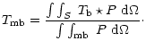
![]() )
over-estimates the actual physical line intensity derived from the observations. Several methods have been proposed to correct from these effects (see Bensch et al. 2001a for a recent review) but most of them require additional observations to be conducted on larger scale and generally smaller telescopes.
)
over-estimates the actual physical line intensity derived from the observations. Several methods have been proposed to correct from these effects (see Bensch et al. 2001a for a recent review) but most of them require additional observations to be conducted on larger scale and generally smaller telescopes.
In this work, we have used an approximation which consists of assimilating the source to a uniform disk-like emitter of brightness temperature
![]() .
If the complete beam of the instrument is known, it is possible to calculate the ratio between
.
If the complete beam of the instrument is known, it is possible to calculate the ratio between
![]() and the real
and the real
![]() as a function of the source size. The 30-m beam is modelled according to Greve et al. (1998) as the superimposition of a main beam and three extended error beams:
as a function of the source size. The 30-m beam is modelled according to Greve et al. (1998) as the superimposition of a main beam and three extended error beams:
| (A.5) |
|
|
3 mm | 1.3 mm | ||
| (
|
|
|
|
|
| 26.2 | 0.67 | 0.47 | 1.00 | 0.42 |
| 30 | 0.77 | 0.54 | 1.02 | 0.43 |
| 46 | 1.00 | 0.70 | 1.06 | 0.45 |
| 60 | 1.04 | 0.73 | 1.10 | 0.46 |
| 90 | 1.05 | 0.74 | 1.20 | 0.51 |
| 120 | 1.05 | 0.74 | 1.32 | 0.56 |
| 150 | 1.06 | 0.74 | 1.44 | 0.60 |
| 180 | 1.07 | 0.75 | 1.54 | 0.65 |
| 240 | 1.08 | 0.76 | 1.68 | 0.71 |
| 600 | 1.14 | 0.80 | 1.90 | 0.80 |
| 6000 | 1.43 | 1.00 | 2.38 | 1.00 |
To estimate the accuracy of this crude approximation, we compared it to a more accurate correction used by Falgarone et al. (1998) and Bensch et al. (2001b) on their data. We found an agreement within 10% for the brightness temperatures at 1.3 mm, where the error beam contamination is rather significant, and within 7% at 3 mm, where the error beam peak-up is much smaller.
For our data, the corrections to
![]() amount to 5-7% at 3 mm and to values in the range 10-70% at 1.3 mm. Emission at a larger distance from the observed position, which is not considered here, might increase the 3 mm correction a little. For most sources the adopted correction at 1.3 mm corresponds to emission extending beyond the first error beam (
amount to 5-7% at 3 mm and to values in the range 10-70% at 1.3 mm. Emission at a larger distance from the observed position, which is not considered here, might increase the 3 mm correction a little. For most sources the adopted correction at 1.3 mm corresponds to emission extending beyond the first error beam (![]() 2
2![]() diameter). One of the greatest limitations of the method shows up for elongated sources but still the geometrical mean should represent on average the fraction of the source surface picked up beyond the main beam. Despite this sometimes severe limitation, we conclude that our approximate correction reasonably accounts for error beam pick-up and that the residual error on
diameter). One of the greatest limitations of the method shows up for elongated sources but still the geometrical mean should represent on average the fraction of the source surface picked up beyond the main beam. Despite this sometimes severe limitation, we conclude that our approximate correction reasonably accounts for error beam pick-up and that the residual error on ![]() is significantly smaller than the error resulting from using either
is significantly smaller than the error resulting from using either
![]() or
or
![]() .
.
Our spectral baselines are affected by standing waves (resulting from multiple reflexions along the optical paths) and by discontinuities in the autocorrelator (AC) baseline (gain mismatch between sub-bands, also known as platforming).
The platforming can be efficiently corrected if a wider band backend (here a filter bank) is connected in parallel. This permits us to provide an accurate 0-level to each sub-band, independent of baseline ripples that are seen equivalently in both spectrometers. A sub-band readjustment based on 0-order baselines separately estimated in each sub-band of the AC alone would indeed alter the wideband standing wave pattern and would thus bias any further correction of this additional effect.
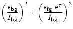
The error estimate on the opacities calculated in Paper I is based on the following formalism for the mid-IR emission:
![\begin{figure}
\par\includegraphics[width=15.5cm,clip]{MS10625f1.eps} \end{figure}](/articles/aa/full/2002/05/aa10625/img41.gif)
![\begin{figure}
\par\includegraphics[angle=270,width=17cm,clip]{MS10625f4.eps}\\ [4mm]
\includegraphics[angle=270,width=17cm,clip]{MS10625f5.eps} \end{figure}](/articles/aa/full/2002/05/aa10625/img45.gif)
![\begin{figure}
\par\includegraphics[angle=270,width=17cm,clip]{MS10625f6.eps} \end{figure}](/articles/aa/full/2002/05/aa10625/img48.gif)
![\begin{figure}
\par\includegraphics[width=17.3cm,clip]{MS10625f8.eps} \end{figure}](/articles/aa/full/2002/05/aa10625/img50.gif)
![\begin{figure}
\par\includegraphics[width=11.5cm,clip]{MS10625f10.eps} \end{figure}](/articles/aa/full/2002/05/aa10625/img56.gif)
![$\displaystyle P = \sum_{i=0,3}~P_{i} =
\sum_{i=0,3}~\frac{w_{i}}{\Omega_{i}}~{\rm exp\left[-ln2~(2\theta / \theta_{\it i})^2\right]} ~{\rm d}\theta$](/articles/aa/full/2002/05/aa10625/img99.gif)
![$\displaystyle T_{\rm mb} = \frac{T_{\rm b}}{\beta_{\rm0}}~
\left[1-\sum_{i=0,3}\beta_{i}~
{\rm exp\left[-ln2~(\theta_s/\theta_{\it i})^2\right]}\right]$](/articles/aa/full/2002/05/aa10625/img103.gif)
![$\displaystyle \left(\frac{\epsilon}{I_{\rm tot}}\right)^2~\left[
\frac {1}{\beta}+\frac{1-\beta~{\rm e}^{-\tau}}{\beta^2}~
({\rm e}^{\tau})^2 \right]\cdot$](/articles/aa/full/2002/05/aa10625/img119.gif)