A&A 378, 327-344 (2001)
DOI: 10.1051/0004-6361:20011166
P. A. Fridman - W. A. Baan
ASTRON, Netherlands Foundation for Research in Astronomy, and Westerbork Observatory, Postbus 2, 7990AA Dwingeloo, The Netherlands
Received 8 June 2001 / Accepted 20 August 2001
Abstract
Various methods of radio frequency interference (RFI) mitigation methods at radio astronomy telescopes are being considered. Special attention is given to real-time processing algorithms. Computer simulations and observational results are used to describe the applicability of these methods. Best results can be achieved when the RFI mitigation procedures are adapted to the particular radio telescope, the type of observations, and the peculiarities of the RFI environment. A combination of different linear and non-linear methods in the temporal and frequency domains, with and without the use of reference antennas, may give considerable suppression of strong RFI.
Key words: techniques: interferometric, miscellaneous - methods: statistical, numerical, miscellaneous
The vulnerability of radio astronomy stations to radio frequency interference (RFI) has been described in a number of publications (Pankonin & Price 1981; Waterman 1984; Galt 1990; Maddox 1995; CRAF (Committee on Radio Astronomy Frequencies) 1997; Spoelstra 1997; Kahlmann 1999; Cohen 1999). The received signals of interest are extremely weak: the typical signal-to-noise ratio (SNR) is generally -30 dB or less and can be as low as -60 dB. As a consequence of their high sensitivity, radio telescopes are also susceptible to interfering signals from transmitters in adjacent and nearby bands. The influence of RFI on a radio astronomy measurement ranges from total disruption by saturation of the receiver to very subtle distortions of the data. While broadband RFI raises the general noise level of receivers, thus degrading its sensitivity, any narrow-band RFI may imitate spectral lines. For weak interfering signals the degradation of the data may be found only after considerable off-line data processing, and may result in false scientific observations.
Radio astronomers are also interested in parts of the radio spectrum that have not been allocated for passive use, because broad-band and narrow-band signals can be found across the whole spectrum. There is a common practice at radio-astronomical stations to monitor the RFI environment in those bands and choose observation times and frequency bands so as to receive the minimum possible man-made noise. Investigations of the different types of RFI indicate that in some cases it is possible to counteract them actively and avoid contamination of the radio astronomical signals. The combined application of analogue and digital (linear and non-linear) processing can significantly improve the quality of the observational data.
It is important to mention at this time that there is no universal method of RFI mitigation in radio astronomy observations. In particular, the applicability and the success of certain mitigation procedures depend on a number of factors:
1. The type of radio telescope - Single dish operations, or connected interferometry, or Very Long Baseline Interferometry. Single dish radio telescopes are especially vulnerable to RFI because all incoming RFI, entering by scattering or reflection, enters the system coherently. The data obtained with interferometer systems suffer from RFI to a lesser degree (Thompson 1982), but any noise power measurements made at each of the antennas for calibration purposes will be distorted by the RFI.
2. The type of observations - Continuum or spectral operations. For continuum observations it is possible to sacrifice some part of the data stream affected by RFI and save the remaining part with some loss of observing efficiency. For spectral observations the narrow-band RFI and the signal-of-interest can be placed in the same spectral region, such that editing in the spectrum can be done. If they are superposed, it is impossible to delete this particular part of the spectrum.
3. The type of ![]() - Impulse-like bursts, narrow-band or wide-band RFI. Theoretical considerations and experimental data show that RFI may be represented as a superposition of two types of waveforms: 1) impulse-like bursts and 2) long narrow-band random oscillations (Middleton 1972, 1977; Lemmon 1997). Figure 1 gives examples of the waveforms of various sorts of RFI.
- Impulse-like bursts, narrow-band or wide-band RFI. Theoretical considerations and experimental data show that RFI may be represented as a superposition of two types of waveforms: 1) impulse-like bursts and 2) long narrow-band random oscillations (Middleton 1972, 1977; Lemmon 1997). Figure 1 gives examples of the waveforms of various sorts of RFI.
![\begin{figure}
\par\includegraphics[height=10cm,width=8.8cm,clip]{H2928F1.eps}
\end{figure}](/articles/aa/full/2001/40/aah2928/img26.gif) |
Figure 1: Examples of RFI waveforms in the receiver output versus time: a) and b) impulse-like RFI; c) radar impulses; d) narrow-band RFI. |
| Open with DEXTER | |
The goal of this paper is to consider various mitigation methods and evaluate their applicability and consider how much they may help to decrease the impact of RFI on the astronomical data. These methods are all based on the characteristics of modern digital signal processing algorithms and the techniques that are commonly used at existing radio telescopes. Right at the start it should be mentioned that all methods of RFI mitigation will be more effective with stronger signals; it becomes increasingly difficult to detect and suppress weaker RFI signals.
In evaluating the methodologies for excising or partly suppressing RFI in the data, there are three main options:
1. Rejection in the Temporal Domain. This type of RFI excision is most effective when dealing with strong and short (spiked) bursts of RFI. Sampling with sufficiently high frequency and subsequent thresholding may give good results. More complex processing such as the cumulative sum method (CUSUM) (Basseville & Nikiforov 1993; Fridman 1996) unites thresholding techniques and adaptive smoothing and provides more flexibility and effectiveness. Weak and long-lasting RFI signals are problematic because the threshold methods in the temporal domain do not work in this case. This type of RFI might be suppressed by frequency rejection methods, which have limited applicability in spectral line observations.
2. Frequency rejection. The whole receiver bandwidth is divided in many channels (using a filterbank or digital correlator techniques) and the channels with RFI are suppressed. This type of RFI excision can only satisfy observational objectives if there is no special spectral line information in the rejected channels. If the RFI signal is concentrated in a few spectral channels, their rejection would not impact strongly on the radiometric sensitivity. If the RFI signal in spectral line observations coincides with the spectral window of interest, the RFI cannot be simply excised because the signal-of-interest will be also excised. If a time-frequency analysis shows that RFI is intermittent (with less than 100% duty cycle), the excision of this RFI can be efficient. In general, adaptive interference cancellation using an auxiliary reference antenna is more effective as a form of spatial filtering.
3. Spatial filtering. Spatial filtering methods use the difference in the direction-of-arrival (DOA) of the astronomical signal-of-interest (SOI) and the RFI. This type of adaptive interference cancellation is similar to the adaptive noise cancellation (ANC) techniques that can be useful for single dish observations using an auxiliary reference antenna pointing off-source. The RFI emission from spatially localized sources could be suppressed using multi-element radio interferometers based on an adaptive array philosophy, where zeros of a synthesized antenna pattern coincide with the DOAs of undesirable signals (adaptive nulling techniques). This approach is being considered for some new-generation radio telescopes (van Ardenne 2000; Bregman 2000). There are some limitations in using this technique for large radio interferometers using sparse antenna arrays with phase-only computer control, which will result in a complex impact on the imaging process. One of the possible applications for this technique could be a tied-array (phased-array) mode, where only one output (two polarizations X, Y or R, L) is produced for use in VLBI or pulsar observations.
Spatial filtering is effective when the RFI is strongly correlated at the individual antennas of the radio telescope, which may be the case for common radar and communications half-wavelength phased-arrays.
Single dish radio telescopes with large antennas employ total power receivers as their output, which is particularly susceptible to RFI, because it is 100% correlated at the antenna feed. Therefore, the RFI power is fully added to the system and to the desired radio source noise power. Even very weak RFI will be dangerous after long averaging by mimicking wanted astronomical signals.
RFI at the sites of VLBI system separated by hundreds and thousands of kilometers, are practically uncorrelated. The impact of RFI at the correlator output is an increased variance. This change in the variance will be significant when the RFI power becomes comparable with the system noise power.
Connected interferometers form an intermediate type of radio telescope. For these systems the RFI at nearby adjacent antennas (with less than 100 m separation) is highly correlated, but it becomes less correlated at larger separations (baselines) of 1 km and especially at baselines from 10-100 km. Because of non-continuous spacings, the effectiveness of the adaptive nulling technique cannot be as high as that of the continuous-like half-wavelength phased arrays.
When evaluating a certain RFI mitigation method, the following two questions need to be asked:
a. What is the level of suppression of the RFI signal?
b. What is the loss of the signal-of-interest as a result of the RFI mitigation also including the total amount of data loss?
The general parameters that describe the method and quantify the results of RFI suppression are the following:
1. The intensity of the RFI is characterized by the input ratio of the system-noise variance to the RFI variance:
 |
(1) |
2. The bandwidth occupied by an RFI signal is characterized by the ratio of signal-of-interest (or receiver) bandwidth to the RFI bandwidth:
 |
(2) |
3. The processing gain obtained after RFI suppression is characterized by the ratio:
 |
(3) |
4. The loss arising from the RFI suppression relative to the ideal situation (no
RFI) is:
 |
(4) |
where ![]() is the receiver bandwidth,
is the receiver bandwidth,
![]() is the bandwidth occupied by the RFI,
is the bandwidth occupied by the RFI,
![]() is the system-noise variance, and
is the system-noise variance, and
![]() is the RFI variance. The signal-to-noise ratio (SNR) is determined as the ratio of the radio telescope output resulting from the SOI to the rms of the fluctuations at this output.
is the RFI variance. The signal-to-noise ratio (SNR) is determined as the ratio of the radio telescope output resulting from the SOI to the rms of the fluctuations at this output.
![\begin{figure}
\par\includegraphics[height=6cm,width=5.6cm,clip]{H2928F2.eps}
\end{figure}](/articles/aa/full/2001/40/aah2928/img34.gif) |
Figure 2: Time-frequency plane of telescope data. The grey areas represent the system noise, and the black areas represent data with RFI. |
| Open with DEXTER | |
In this section a number of RFI suppression methods will be considered. An evaluation of the processing gain and loss parameters for each of these methods can be found in the corresponding section in the Appendix (Sect. 6).
A general description of a telescope input signal x(t) is
| (5) |
The signals received by a radio telescope can be represented in a simplified form in the time-frequency (t - F) plane (Fig. 2), where the grey parts are the areas free from RFI with only the presence of
![]() ,
and where the black parts correspond to the presence of RFI. Thus a time-frequency analysis of x(t) with sufficiently high resolution in both axes must be performed in order to detect these "black'' zones and excise them.
,
and where the black parts correspond to the presence of RFI. Thus a time-frequency analysis of x(t) with sufficiently high resolution in both axes must be performed in order to detect these "black'' zones and excise them.
It is difficult to prescribe a time resolution ![]() and a frequency resolution
and a frequency resolution ![]() for detection of all possible varieties of RFI. However, some recommendations can be made for the range of these values:
for detection of all possible varieties of RFI. However, some recommendations can be made for the range of these values:
![]() s and of
s and of
![]() kHz. Especially this last number is conditional and depends on the receiver bandwidth
kHz. Especially this last number is conditional and depends on the receiver bandwidth
![]() ,
which may vary from dozens of kHz to hundreds of MHz. When the ratio of excised data to the total amount of data
,
which may vary from dozens of kHz to hundreds of MHz. When the ratio of excised data to the total amount of data
![]() is less than 5-10%, where T is the integration time, this method of RFI mitigation can be used well for continuum observations. The quantitative estimates for the gain and loss are given in the Appendix.
is less than 5-10%, where T is the integration time, this method of RFI mitigation can be used well for continuum observations. The quantitative estimates for the gain and loss are given in the Appendix.
![\begin{figure}
\par\includegraphics[height=12cm,width=8.2cm,clip]{H2928F3.eps}
\end{figure}](/articles/aa/full/2001/40/aah2928/img47.gif) |
Figure 3:
Source scans made at the RATAN-600 at
|
| Open with DEXTER | |
![\begin{figure}
\par\includegraphics[height=10cm,width=8.8cm,clip]{H2928F4.eps}
\end{figure}](/articles/aa/full/2001/40/aah2928/img50.gif) |
Figure 4:
The time evolution of the autocorrelation (power) spectra affected by RFI taken with the WSRT at 6 cm receiver with bandwidth
|
| Open with DEXTER | |
![\begin{figure}
\par\includegraphics[height=10cm,width=8.8cm,clip]{H2928F5.eps}
\end{figure}](/articles/aa/full/2001/40/aah2928/img51.gif) |
Figure 5: The time evolution of the cross-spectrum magnitudes for the data in Fig. 4: a) the dirty data without RFI excision, b) the cleaned data after RFI excision. |
| Open with DEXTER | |
Figure 3 illustrates some RFI mitigation results in the temporal domain during observations with the RATAN-600 telescope (Fridman & Berlin 1996). The procedure uses post-detection sampling with a time resolution of 4 ![]() s and an RFI detection and excision method by thresholding at the
s and an RFI detection and excision method by thresholding at the
![]() level. Subsequent time averaging to obtain the necessary SNR gain
level. Subsequent time averaging to obtain the necessary SNR gain
![]()
![]() provides additional suppression of impulse-like RFI.
provides additional suppression of impulse-like RFI.
Figures 4-6 give examples of RFI excision in the frequency-domain at the Westerbork Synthesis Radio Telescope (WSRT).
The data were recorded during a VLBI session at the WSRT at 6 cm on 8 June 2000. The baseband outputs of two radio telescopes (RT1 and RT2) were digitized and their power spectra were calculated with the help of a DSP processing unit (TMS320C6201, Signatec PMP-8 board). Figures 4a and 4b represent the autocorrelation spectra including RFI. The cross-correlation spectrum of this raw data is represented in Fig. 5a, while the cleaned cross-spectrum after RFI excision is shown in Fig. 5b. The time-averages of the cross-correlation spectra of Fig. 5 are given on a logarithmic scale in Figs. 6a,b. The time-averaged dirty and clean cross-correlation functions (magnitudes) are shown in Figs. 6c,d. The five-fold difference in the magnitude in Fig. 6c shows that a large false correlation occurs in the presence of RFI. The peak in the cross-correlation function in Fig. 6d corresponds to a weak (but real) radio source.
![\begin{figure}
\par\includegraphics[height=8cm,width=9.0cm,clip]{H2928F6.eps}
\end{figure}](/articles/aa/full/2001/40/aah2928/img56.gif) |
Figure 6: The averaged cross-correlation spectra corresponding to Figs. 4 and 5 are given on a logarithmic scale in the upper frames: a) no RFI excision applied; b) with RFI excision applied. The averaged cross-correlation functions are given in the bottom frames: c) no RFI excision applied; d) with RFI excision applied. |
| Open with DEXTER | |
Temporally spread and strongly correlated RFI (see Fig. 1d) can be suppressed using cancellation techniques based on estimating the RFI waveform and subsequently subtracting it from the signal+RFI mixture:
| (6) |
![\begin{figure}
\par\includegraphics[height=8cm,width=8.3cm,clip]{H2928F7ss.eps}
\end{figure}](/articles/aa/full/2001/40/aah2928/img59.gif) |
Figure 7: Methods of RFI cancellation using autoclean filtering as described in Sect. 3.2 (frame a) and RFI excision by filtering using a reference channel as described in Sect. 3.3 (frame b)). |
| Open with DEXTER | |
The following example uses WSRT data to describe the use of this autoclean method in the frequency domain. Figures 8a,b display the time evolution of the power spectra at two adjacent WSRT antennas at ![]() = 49 cm. Figures 9a,b show the averaged power spectra corresponding to Fig. 8. The complex instantaneous spectra at each of the two antennas were processed using this "RFI estimation - subtraction'' technique. Figure 9d shows the "dirty'' cross-correlation function (without RFI suppression), while Fig. 9c shows the "cleaned'' cross-correlation function (after RFI suppression).
= 49 cm. Figures 9a,b show the averaged power spectra corresponding to Fig. 8. The complex instantaneous spectra at each of the two antennas were processed using this "RFI estimation - subtraction'' technique. Figure 9d shows the "dirty'' cross-correlation function (without RFI suppression), while Fig. 9c shows the "cleaned'' cross-correlation function (after RFI suppression).
![\begin{figure}
\par\includegraphics[height=9cm,width=8.8cm,clip]{H2928F8s.eps}
\end{figure}](/articles/aa/full/2001/40/aah2928/img60.gif) |
Figure 8:
An example of the time evolution of power spectra with RFI on a logarithmic scale. The bandwidth is |
| Open with DEXTER | |
![\begin{figure}
\par\includegraphics[height=8cm,width=8.0cm,clip]{H2928F8.eps}
\end{figure}](/articles/aa/full/2001/40/aah2928/img61.gif) |
Figure 9: Excision by autoclean filtering of the data given in Fig. 8: a) the averaged power spectrum of RT1, b) the averaged power spectrum of RT2, c) the cross-correlation function after the RFI suppression, and d) the cross-correlation function with RFI present. |
| Open with DEXTER | |
One necessary comment should be made about using these thresholding (Sect. 3.1) and autoclean (this section) methods: the basic form of the system noise spectrum must be known beforehand. Because it is not ideally rectangular, it repeats the form of the receiver transfer function. These algorithms depend on the "quiet'', undisturbed baseband spectrum as a reference in order to compare it with the running spectra with RFI.
An example of a parametric approach to this type of RFI cancellation can be found in Ellingson et al. (2000). In this paper the strong interfering signal of a GLONASS satellite is represented by a parametric model, such that its parameters - Doppler frequency, phase code, and complex amplitude - were calculated for each separate data block. The parametric model of the RFI was then used to calculate an RFI waveform, which was subsequently subtracted from the RFI + noise signal mixture. The signal-of-interest, in this case an OH spectral line at 1612 MHz, was not significantly distorted during the RFI suppression process.
A separate, dedicated reference channel may be used in order to obtain an independent estimate of the RFI signal
![]() .
This technique has been used for a long time in digital signal processing and is called adaptive noise cancelling (ANC) (Widrow & Stearnes 1985). Figure 7b shows a block diagram relating to the application of this type of algorithm. There are two data channels: a main channel with the radio telescope pointing on source and containing the RFI signal, and an auxiliary or reference channel at a separate antenna pointing off source and also containing the RFI signal. While both channels contain the RFI signal, they are not identical due to the different propagation paths and radio receivers. To the procedure now calls for adjusting the RFI signal in the reference channel with the help of an adaptive filter, such that the error signal
.
This technique has been used for a long time in digital signal processing and is called adaptive noise cancelling (ANC) (Widrow & Stearnes 1985). Figure 7b shows a block diagram relating to the application of this type of algorithm. There are two data channels: a main channel with the radio telescope pointing on source and containing the RFI signal, and an auxiliary or reference channel at a separate antenna pointing off source and also containing the RFI signal. While both channels contain the RFI signal, they are not identical due to the different propagation paths and radio receivers. To the procedure now calls for adjusting the RFI signal in the reference channel with the help of an adaptive filter, such that the error signal
![]() .
The value of this error signal is used for adjusting the filter.
.
The value of this error signal is used for adjusting the filter.
This procedure can be applied both in the temporal domain (adaptive filtering) and in the frequency domain using an
![]() adaptation in each frequency bin
adaptation in each frequency bin
![]() procedure. This kind of RFI cancellation is especially useful for spectral line observations, where the RFI and the signal-of-interest occupy the same frequency domain.
procedure. This kind of RFI cancellation is especially useful for spectral line observations, where the RFI and the signal-of-interest occupy the same frequency domain.
Figures 10 and 11 illustrate the results of using the ANC procedure with WSRT data at 428 MHz. Figures 10a,b shows the power spectra at the outputs of the main and the reference channels. Figure 11 shows the cleaned power spectrum of the main channel.
Other examples of the use of a reference channel can be found in Barnbaum & Bradley (1998) and Briggs et al. (2000). The second paper also discusses post-detection RFI suppression. In these papers the complex spectrum of the RFI estimate was obtained with the help of closure relations using four averaged correlator output signals all containing RFI: two polarizations for the main channel and two polarizations for the reference channel. Subsequently the power spectrum estimate of the RFI was subtracted from the power spectrum of the main channel. This method is particularly effective for multi-feed single dish radio telescopes.
![\begin{figure}
\par\includegraphics[height=6.5cm,width=8.0cm,clip]{H2928F10.eps}...
...{2mm}
\includegraphics[height=6.5cm,width=8.0cm,clip]{H2928F11.eps}
\end{figure}](/articles/aa/full/2001/40/aah2928/img66.gif) |
Figure 10: The time evolution of the power spectrum of the main channel of RT1 is given in frame a and of the reference channel of RT2 in frame b. This data is used to obtain the effectiveness of adaptive noise cancellation using a reference channel as given in Fig. 11. |
| Open with DEXTER | |
![\begin{figure}
\par\includegraphics[height=6.5cm,width=8.0cm,clip]{H2928F12.eps}
\end{figure}](/articles/aa/full/2001/40/aah2928/img67.gif) |
Figure 11: The time evolution of the "clean'' power spectrum of the main channel RT1 after applying an adaptive noise cancellation technique with a reference channel. |
| Open with DEXTER | |
Adaptive-nulling of a synthesized pattern in the direction of RFI sources has been widely used in radar and communication systems (smart antennas). This technique can be applied in multi-element radio interferometers (MERIs) but has the following limitations:
1. Radio astronomy MERIs are generally very sparse arrays. The distances between antennas are equal to hundreds and thousands of meters, which is significantly larger than the
![]() separation of ordinary phased-arrays. Therefore, adaptive-nulling is particularly effective for narrow-channel processing (at the kHz level).
separation of ordinary phased-arrays. Therefore, adaptive-nulling is particularly effective for narrow-channel processing (at the kHz level).
2. Radio astronomy MERIs are correlation arrays and are not additive. The antenna pattern is not synthesized in real-time but rather off-line after several (up to 12) hours of tracking the radio source. In principle, it is possible to introduce complex weighting during the image processing stage and do the RFI suppression off-line. But this also means that time averaging during correlation requires the use of small time intervals and narrow bands, so as not to smooth the RFI in frequency and time. This type of processing requires a significant increase of computational power and also requires changes in the image-making software. Several aspects of this problem have been discussed in Leshem et al. (2000).
3. All spatial adaptive-nulling procedures presume that the RFI sources are well localized in space, which is not always the case.
In this section, we discuss some test WSRT observations using a spatial filtering technique based on adaptive complex weighting of the data. The signals from two antennas RT1 and RT2 (Fig. 12) were Fourier transformed and their complex spectra were combined at each frequency bin in order to get an estimate of the RFI. These RFI estimates were then subtracted from each of the RT1 and RT2 signals. The RFI estimates were made, while minimizing the error signals at the subtracted outputs. Subsequently the cross-correlation functions and the corresponding cross-spectra were calculated. Figure 13 shows the results of test observations of 3C 48 at
![]() cm with a sampling frequency of
cm with a sampling frequency of
![]() MHz. Figures 13c,d show the cleaned spectrum after RFI subtraction, and the dirty spectrum without RFI suppression.
MHz. Figures 13c,d show the cleaned spectrum after RFI subtraction, and the dirty spectrum without RFI suppression.
Real-time adaptive-nulling techniques are particularly suitable for the future generation of radio telescopes using phased-array techniques (van Ardenne et al. 2000; Bregman 2000). It is also possible to apply adaptive-nulling in existing MERIs operating in a so-called tied-array mode, for example, during VLBI operations or pulsar observations (see Moran 1995).
![\begin{figure}
\par\includegraphics[height=8.0cm,width=7.9cm,clip]{H2928F18.eps}
\end{figure}](/articles/aa/full/2001/40/aah2928/img71.gif) |
Figure 12:
The time evolution of power spectra for two antennas a) RT1, b) RT2. The wavelength of the data is |
| Open with DEXTER | |
![\begin{figure}
\par\includegraphics[height=8.0cm,width=8.0cm,clip]{fig13.eps}
\end{figure}](/articles/aa/full/2001/40/aah2928/img73.gif) |
Figure 13:
The averaged power spectra for antennas RT1 and RT2 is given in a) and b) corresponding to the data in Fig. 12. The complex cross-correlation function between RT1 and RT2 is given (in magnitudes) in c) the cleaned spectrum, and in d) the dirty spectrum (
|
| Open with DEXTER | |
![\begin{figure}
\par\includegraphics[height=6.0cm,width=8.0cm,clip]{H2928F14.eps}
\end{figure}](/articles/aa/full/2001/40/aah2928/img74.gif) |
Figure 14: The unmodified (solid line) and the phase-only adapted (dashed line) main-beam pattern for a 14 element array with 144 m spacings at a central frequency of 1420 MHz. |
| Open with DEXTER | |
![\begin{figure}
\par\includegraphics[height=6.0cm,width=8.0cm,clip]{H2928F15.eps}
\end{figure}](/articles/aa/full/2001/40/aah2928/img75.gif) |
Figure 15:
The unmodified (solid line) and the phase-only adapted (dashed line) beam pattern of the 14 element array in Fig. 14 in the direction of the RFI source at
|
| Open with DEXTER | |
![\begin{figure}
\par\includegraphics[height=6.0cm,width=8.0cm,clip]{H2928F16.eps}
\end{figure}](/articles/aa/full/2001/40/aah2928/img76.gif) |
Figure 16:
The unmodified (solid line) and the phase-only adapted (dashed line) beam pattern of the 14 element array in Fig. 14 in the direction of the RFI source at
|
| Open with DEXTER | |
![\begin{figure}
\par\includegraphics[height=6.0cm,width=8.0cm,clip]{H2928F17.eps}
\end{figure}](/articles/aa/full/2001/40/aah2928/img77.gif) |
Figure 17: The distribution of the phase corrections at the 14 antennas corresponding to the adapted beam patterns described in Figs. 14-16. |
| Open with DEXTER | |
An example of such an application using a genetic algorithm for solving the optimisation problem is represented in Figs. 14-16. Figure 14 shows the calculated unmodified (solid line) and adapted (dashed line) beam patterns of a linear MERI with 14 antenna at separations of 144m and at a central frequency of f0 = 1420 MHz. The direction of arrival (DOA) of the signal of interest (SOI) is at ![]() and the DOA of two sources of RFI are at
and the DOA of two sources of RFI are at
![]() and
and
![]() ,
respectively. Figures 15 and 16 show fragments of the beam patterns in the two directions of the RFI, which were purposely chosen to coincide with the maxima of the unmodified side lobes. The distribution of the phase corrections corresponding to this adapted pattern is given in Fig. 17.
,
respectively. Figures 15 and 16 show fragments of the beam patterns in the two directions of the RFI, which were purposely chosen to coincide with the maxima of the unmodified side lobes. The distribution of the phase corrections corresponding to this adapted pattern is given in Fig. 17.
The method of RFI excision based on a probability distribution analysis of the output signal of the radio telescope has applications for both spectral line and continuum observations (Fridman 2001). The signals of the system noise and the radio source generally have a Gaussian distribution with a zero mean. Fourier transformation of such an ideal signal also gives real and imaginary components in every spectral bin, that are Gaussian random values with zero means. On the other hand, the instantaneous power spectrum (the square of magnitude of the complex spectrum) has an exponential distribution, which can be described as a chi-squared distribution with two degrees of freedom.
The presence of an RFI signal modifies the ideal input signal further and yields a change of its statistics. The modified power spectrum will now have a non-central chi-squared distribution with two degrees of freedom. Standard radio astronomy practices employ significant averaging of the power spectrum, which would again convert the probability distribution of the averaged power spectrum into a Gaussian distribution. Therefore, only real-time analysis by means of DSP processing of the distribution before averaging will allow a separation of the two signal components.
Test observations at the WSRT have been used to demonstrate the effectiveness of this digital spectral analysis. The baseband (0-1.25 MHz) signal at the analogue output of the WSRT-DLB subsystem for one of the antennas (RT6) has been digitized in a 12-bit analogue to digital converter and then supplied to a Signatec PMP-8 system, where the FFT and the averaged statistical parameters are calculated.
Figure 18 shows the results of these test observations of the 21 cm HI line in the direction of the Crab Nebula. Since no transmissions are allowed in the 1400-1427 MHz band, an artificial CW RFI signal was transmitted in the direction of the RT6 antenna from the WSRT control building. The power spectra of Fig. 18 show the non-processed data and the processed data generated simultaneously. The clear RFI signal in the non-processed data is suppressed by about 17 dB in the processed spectrum.
This method can be used both for spectral line and continuum observations. In the continuum case, parts of the spectrum with a "non-Gaussian signature'' may be blanked or filtered out. However, it should be mentioned that reliable estimates of the higher moments of the data (or cumulants) will require more averaging than for the first moment (the mean). This is important for mitigation of the weak RFI. Large averaging intervals will smooth the variability of the RFI and will yield estimates with a considerable bias. Therefore, a trade-off should be adopted, which implies some limitations on the detection and limited excision of weak RFI signals. This principle applies equally to other RFI mitigation methods: stronger RFI signals can be easier detected and suppressed.
![\begin{figure}
\par\includegraphics[height=8.0cm,width=8.0cm,clip]{H2928F13.eps}
\end{figure}](/articles/aa/full/2001/40/aah2928/img79.gif) |
Figure 18: RFI excision based on a probability analysis of the signal. The WSRT data were taken with bandwidth = 1.25 MHz, half-sampling frequency = 1.563 MHz, and frequency resolution = 3.052 kHz. a) A total power spectrum of a galactic HI emission spectrum and an absorption line towards the Crab Nebula at 1420.4 MHz with an artificial RFI signal at 1420.397 MHz; b) The same data after RFI excision made simultaneously; c) The spectral window around the spectral line (channels 30-100) with superposed spectra from a) and b) and a spectrum without any RFI. |
| Open with DEXTER | |
In this section we consider the effectiveness and applicability of the various RFI mitigation methods for different types of telescopes and telescope operations. There are three principal stages in the astronomical data-taking process at which mitigation methods can be used:
1. Real-time pre-detection and pre-correlation baseband processing is based on time-frequency analysis and adaptive noise cancellation using reference channels. This approach requires the implementation of fast digital processing techniques (>100 GIPs), which can already be achieved with modern digital signal processing hardware based on DSP and FPGA devices. However, the implementation of these RFI mitigation techniques may not be easy and may sometimes be technically impossible in the existing backends.
2. Real-time post-correlation processing techniques may introduce time-frequency analysis as part of the correlation process and before data averaging. The implementation of these methods will also require special hardware as part of the existing backends.
3. Off-line post-detection and post-correlation processing techniques, such as adaptive-nulling and those using closure relations and reference signals, may capitalize on the differences in the spatial signatures of the signal-of-interest and the RFI signal. This approach is attractive from a practical point, because it requires no change in the radio telescope backend hardware. However, these methods may be less effective than real-time processing.
It should be mentioned here that applications of these methods do not exclude other technical measures, such as the development of front-ends with high linearity and of analogue filters with low insertion (<
![]() )
losses and high stop-band attenuation (>
)
losses and high stop-band attenuation (>![]() ).
).
Single dish telescopes are most susceptible to RFI signals. Depending on the type of observations and on the available electronics, the following methods may be considered for application:
1. Continuum observations are best served with post-detector blanking and filtering with high temporal (at least microseconds) and frequency (less than 1 kHz) resolution.
2. Spectral observations are best served with methods using a reference antenna (or reference feed). In this case an estimate of the RFI signal may be subtracted from the input signal with real-time adaptive filter processing, or with off-line processing using the complex closure-amplitudes of the correlated data.
Analysis of the higher-order statistics of the received signals is an effective method of RFI detection and mitigation, but it requires some considerable modifications in the existing spectrometers, which measure only the mean of the spectra. New generations of radio astronomy spectrometers should also determine the higher moments of the spectrum. Using the polyspectra analysis may also be useful for radio interferometers experiencing strong (atmospheric) phase errors.
Interferometers such as the WSRT, VLA, GMRT, and MERLIN, are less vulnerable with respect to man-made RFI. Modulation of the RFI by routine fringe-stopping and decorrelation by delay compensation procedures constitute a natural suppression of weak RFI signals in interferometers. Strong RFI signals cause a significant change of the noise-variance before correlation and hence they distort the complex visibilities of the correlator output. Thus pre-correlation real-time blanking and filtering with and without a reference antenna can result in a considerable gain in RFI suppression.
RFI suppression using post-correlation complex weighting (adaptive nulling) may be also effective for interferometers as in the case of ordinary half-wavelength phased-arrays, but it will change the amplitude-phase structure of image visibilities. Therefore continuous "book-keeping'' of these weights is necessary, in order to take them into account at a later time during the image synthesis stages of CLEAN + self-calibration procedures.
Spatial filtering is effective only if the RFI is significantly correlated at the radio interferometer antenna sites. This is likely not to be the case generally, because of multi-path propagation effects and other limitations due to the base - radio source - RFI source geometry. The use of a special reference antenna pointing at the RFI source is particularly attractive when subsequent post-correlation processing is used based on complex amplitude-closure relations. This procedure does not interfere with the existing radio telescope infrastructure and gives a high signal-to-noise ratio with respect to the RFI.
VLBI observations are most robust to RFI due to the very large baselines, because the RFI signals are practically uncorrelated at the different stations. The calibration data at each site is also susceptible to RFI, such as is the case for single dish observations. Therefore, RFI blanking at each of the VLBI sites may be considered as desirable for the new generation of VLBI video converters (Mark-V).
A quantitative evaluation of the effectiveness of the different methods is not always possible. In the first place, the RFI mitigation algorithms are often non-linear procedures. Secondly, the suppression of an RFI signal achieved with a certain method depends on the fractional intensity of the RFI signal (i.e. the INR) and its spatial, temporal and spectral characteristics. The extreme example is the simplest method of thresholding in the temporal or frequency domains. If we assume that the RFI signal is 100 dB(!) higher than the system noise and we ignore the non-linearities in the receiver, this "100 dB'' RFI can easily be detected and excised. As a result we have a suppression gain of ![]() 100 dB, because there is no RFI left over at all. However, there will be a certain growth of the noise standard deviation at the correlator or detector output due to a deletion of a number of data samples. The effect will thus be visible as a loss in the SNR.
100 dB, because there is no RFI left over at all. However, there will be a certain growth of the noise standard deviation at the correlator or detector output due to a deletion of a number of data samples. The effect will thus be visible as a loss in the SNR.
Therefore, a simplified approach in the evaluation of the effectiveness of the RFI mitigation method is affected by its dependence on the particulars of the RFI situation. The estimates in the Appendix provide the approximate bounds for the gain and loss. A practical limit for each method depends on the INR. Sometimes it is not possible to remove the RFI below the noise level of the data. This is also useful for understanding the cumulative effect of RFI mitigation at various stages of the data acquisition process, where different methods may be applied simultaneously, such as filters in the frontend, real-time processing, post-correlation processing, etc. The RFI characteristics change after each stage of RFI suppression. The total RFI is thus not the linear sum of what is maximally possible at each stage but rather a sum of what is practically possible considering the parameters of the RFI signal encountered.
An RFI database should be created at each radio telescope in order to provide guidance for observational procedures and for choosing appropriate RFI mitigation methods. The combination of a database and hardware/software facilities forms the basis for an RFI mitigation system and should be used at terrestrial radio telescopes operating in hostile electro-magnetic environments.
1. While there are different types of radio telescopes, different observational procedures and different types of RFI signals,there is no universal method of RFI mitigation.
2. A choice of the proper RFI mitigation method should be made taking into account the particulars of the RFI environment of each site.
3. The application of digital RFI mitigation techniques in radio astronomy is still at the beginning of its development. However, there are encouraging results with theoretical and computer simulations, and with on-line and off-line data processing.
4. Existing single-dish telescopes and multi-element radio interferometers should be equipped with RFI mitigation facilities in order to fully realize their observational potential.
5. The next generation radio telescopes should be designed from the outset with RFI mitigation facilities in place.
6. There are a number of points in the astronomical data-taking process where RFI mitigation methods may be applied. Pre-processing occurs between the detectors and the correlator. Real-time processing may utilize the processing capability of the correlator in order to reduce the effects of the RFI. Post-processing techniques may use excising techniques or the data from reference antennas.
Estimates of the gain, which is the degree of RFI suppression, and the loss, which is the degradation of the signal-of-interest after processing, are presented in this section for different methods of RFI mitigation.
Let us consider the time-frequency
![]() -plane of Figure 2, where grey areas correspond to a system noise (no RFI) and black areas indicate the presence of RFI. The total number of data points in the
-plane of Figure 2, where grey areas correspond to a system noise (no RFI) and black areas indicate the presence of RFI. The total number of data points in the
![]() -plane is M. A fraction
-plane is M. A fraction
![]() is occupied by RFI, where SRFI is the total area occupied by RFI, and
is occupied by RFI, where SRFI is the total area occupied by RFI, and
![]() is the total area of the
is the total area of the
![]() -plane. The
-plane. The
![]() -plane is used for data averaging to get a gain
-plane is used for data averaging to get a gain ![]()
![]() in the signal-to-system noise ratio after correlation (or total power detector, TPD).
in the signal-to-system noise ratio after correlation (or total power detector, TPD). ![]() is naturally less than one,
is naturally less than one,
![]() because otherwise the excision process will also excise the signal-of-interest.
because otherwise the excision process will also excise the signal-of-interest.
Let us first consider the idealized situation: all RFI are 100% detected and excised. What are the benefits in terms of gain and loss as defined by formulas 3 and 4? Let
![]() ,
and
,
and
![]() be the antenna signal, the system noise, and the RFI spectral power densities, respectively, with
be the antenna signal, the system noise, and the RFI spectral power densities, respectively, with
![]() The rms of the fluctuations at the output of the correlator (or the TPD) in the absence of RFI is
The rms of the fluctuations at the output of the correlator (or the TPD) in the absence of RFI is
![]()
![]() The signal-to-noise ratio (SNR) in the absence of RFI is
The signal-to-noise ratio (SNR) in the absence of RFI is
![]()
The rms and the SNR in the presence of RFI is expressed as
 ,
,
The optimally expected gain for single-dish observations can be expressed as the SNR ratio of the total power detector (radiometer) output with a cleaning procedure (subtraction of RFI estimates) compared to the SNR without this subtraction:
![$\displaystyle G_{\rm CLN}=\frac{\left[ \left( Q_{1}+Q_{2}\right) ^{2}-2Q_{1}-Q_{2}\right]
^{1/2}(Q_{1}^{2}+Q_{2})^{1/2}}{Q_{1}(Q_{1}+Q_{2})},$](/articles/aa/full/2001/40/aah2928/img120.gif) |
(7) |
![$\displaystyle R_{\rm CLN}=\frac{\left[ \left( Q_{1}+Q_{2}\right) ^{2}-2Q_{1}-Q_{2}\right]
^{1/2}}{(Q_{1}+Q_{2})},$](/articles/aa/full/2001/40/aah2928/img121.gif) |
(8) |
When
![]() ,
then
,
then
![]() because both the wanted signal and the RFI have the same bandwidth and during an autoclean procedure the signal is subtracted from itself. Therefore, this RFI excision method is only useful when Q2>1 for continuum observations. In the case of spectral-line observations, where the xRFI occupies the same spectral region as the signal
because both the wanted signal and the RFI have the same bandwidth and during an autoclean procedure the signal is subtracted from itself. Therefore, this RFI excision method is only useful when Q2>1 for continuum observations. In the case of spectral-line observations, where the xRFI occupies the same spectral region as the signal
![]() and
and
![]() ,
the RFI rejection should be done using a reference channel.
,
the RFI rejection should be done using a reference channel.
![\begin{figure}
\par\includegraphics[height=10.0cm,width=8.8cm,clip]{H2928F19s.eps}
\end{figure}](/articles/aa/full/2001/40/aah2928/img129.gif) |
Figure 19:
The effectiveness of RFI suppression with filtering but without using a reference channel. The gain and loss are plotted using
|
| Open with DEXTER | |
The more complicated case of a correlation interferometer will now be considered, where the RFI signals at both sites are not 100% correlated.
![]() is the correlation coefficient between the RFI waveforms at the two sites. This
is the correlation coefficient between the RFI waveforms at the two sites. This
![]() is a time-varying parameter (
is a time-varying parameter (
![]() ), which depends on parameters as the distance between the antennas, the propagation effects, the pointing of the antennas, the fringe stopping procedure, etc. The impact of the RFI is double-sided: it affects both the cross-correlation (cross-spectrum) bias and the growth of the variance. For a long-baseline interferometers such as the VLBI arrays and MERLIN,
), which depends on parameters as the distance between the antennas, the propagation effects, the pointing of the antennas, the fringe stopping procedure, etc. The impact of the RFI is double-sided: it affects both the cross-correlation (cross-spectrum) bias and the growth of the variance. For a long-baseline interferometers such as the VLBI arrays and MERLIN,
![]() is practically equal to zero and the main impact of the RFI is the growth of the variance. For the short-baseline correlation pairs of the WSRT or VLA, the bias of the mean becomes the most important distortion. The three formulas for estimating the processing benefits after RFI suppression using a filtering technique are expressed as:
is practically equal to zero and the main impact of the RFI is the growth of the variance. For the short-baseline correlation pairs of the WSRT or VLA, the bias of the mean becomes the most important distortion. The three formulas for estimating the processing benefits after RFI suppression using a filtering technique are expressed as:
![]() is the ratio of the SNR at the correlator output with the presence of RFI with cleaning and of the SNR with the presence of the RFI but without cleaning:
is the ratio of the SNR at the correlator output with the presence of RFI with cleaning and of the SNR with the presence of the RFI but without cleaning:
 |
(9) |
 |
(10) |
 |
(11) |
![\begin{figure}
\par\includegraphics[height=12.0cm,width=8.8cm,clip]{H2928F20s.eps}
\end{figure}](/articles/aa/full/2001/40/aah2928/img137.gif) |
Figure 20:
The effectiveness of RFI suppression with filtering without a reference channel for a correlation interferometer. The gain, loss, and bias parameters are presented as functions of
|
| Open with DEXTER | |
![\begin{figure}
\par\includegraphics[height=10.0cm,width=8.8cm,clip]{H2928F21.eps}
\end{figure}](/articles/aa/full/2001/40/aah2928/img138.gif) |
Figure 21:
The effectiveness of RFI suppression with a reference channel for single dish systems. The gain and loss are presented as functions of
|
| Open with DEXTER | |
![\begin{figure}
\par\includegraphics[height=14.0cm,width=8.8cm,clip]{H2928F22.eps}
\end{figure}](/articles/aa/full/2001/40/aah2928/img139.gif) |
Figure 22:
The effectiveness of RFI suppression with a reference channel for the case of a correlation interferometer. The gain, loss, and bias are presented as a functions of
|
| Open with DEXTER | |
![\begin{figure}
\par\includegraphics[height=14.0cm,width=8.8cm,clip]{H2928F23.eps}
\end{figure}](/articles/aa/full/2001/40/aah2928/img140.gif) |
Figure 23:
The effectiveness of RFI suppression with reference channel for a correlation interferometer. The gain, loss, and bias are presented as a function of
|
| Open with DEXTER | |
For spectral line observations, where xRFI occupies the same spectral region as the signal
![]() and
and
![]() ,
the RFI rejection should be made with the aid of an auxiliary reference channel. Otherwise the useful coherent signal will be subtracted together with the RFI. The output of this auxiliary channel is described as:
,
the RFI rejection should be made with the aid of an auxiliary reference channel. Otherwise the useful coherent signal will be subtracted together with the RFI. The output of this auxiliary channel is described as:
| (12) |
| (13) |
 |
(14) |
 |
(15) |
 |
(16) |
 |
(17) |
| (18) |
Adaptive nulling is an attractive possibility for multi-element radio interferometric radio telescopes. In order to get a rough estimate of the gains and losses for this type of RFI suppression, we use a simplified approach based on the block diagram of Fig. 24. All processing in the block diagram is made in the frequency domain after the Fourier transform, which is not shown in the diagram itself. In the following we consider a narrow-band situation. Signals from M antennas are supplied to the signal cancelling block, which serves to combine the antenna's signals in order to minimize the signal at the output of this block. This is done to prevent further degradation of the useful signals during the RFI suppression process. This is possible because the direction of arrival (DOA) of a wanted signal is known (prescribed). The outputs of the signal-cancelling block are processed in the RFI-estimation block in order to obtain estimates of the RFI signals, which will later be subtracted from the main antenna's signals and must provide minimal error signals after subtraction.
The algorithm inside the RFI-estimation block is not specific at this point. An adaptive algorithm is needed here, which can be a method of running estimates of the co-variation matrix, the LMS algorithm, or something else. The advantage of the procedure in this block diagram lies in keeping the amplitude and phase structure of the signal-of-interest intact. The subtraction of an RFI-estimate should not affect the wanted radio signal, and there is no need to do special bookkeeping of the complex adaptation coefficients used in the RFI-estimation block. The outputs of subtractor blocks are supplied to the correlator. Delay compensation is expected to happen inside the correlator block and fringe stopping is done before the subtractors.
![\begin{figure}
\par\includegraphics[height=13.0cm,width=7.3cm,clip]{H2928F24.eps}
\end{figure}](/articles/aa/full/2001/40/aah2928/img169.gif) |
Figure 24: A block diagram of the spatial filtering process for RFI suppression. |
| Open with DEXTER | |
| (19) |
| (20) |
![]()
such that
 |
(21) |
| (22) |
| (23) |
| (24) |
 |
(25) |
| (26) |
Before the formation of ![]() a signal cancelling component
a signal cancelling component
![]() matrix
matrix ![]() is introduced, which is written as:
is introduced, which is written as:
 |
(27) |
| (28) |
| (29) |
| (30) |
| (31) |
| (32) |
| (33) |
| (34) |
 |
(35) |
| (36) |
| (37) |
All these figures have been given here for illustrative purposes, in order to describe the effects for a sparse periodic array. Real arrays have much larger inter-element distances and are not so regular (except for the WSRT). Therefore, the expected values for the gain and the loss should be calculated for the particular array-source-RFI geometry and for a particular RFI intensity. The RFI signals also enter the frontend through the antenna sidelobes and the sources are often situated in the near-field zone of the antenna. Therefore, the scenario described above might indeed be too idealized.
![\begin{figure}
\par\includegraphics[height=8.0cm,width=8.8cm,clip]{H2928F71.eps}
\end{figure}](/articles/aa/full/2001/40/aah2928/img207.gif) |
Figure 25:
The power pattern of a 16-element array with interval between elements of
|
| Open with DEXTER | |
![\begin{figure}
\par\includegraphics[height=8.0cm,width=8.0cm,clip]{H2928F72.eps}
\end{figure}](/articles/aa/full/2001/40/aah2928/img209.gif) |
Figure 26:
The output interference-to-noise ratio for a 16-element array at regular intervals of
|
| Open with DEXTER | |
![\begin{figure}
\par\includegraphics[height=8.0cm,width=8.0cm,clip]{H2928F73.eps}
\end{figure}](/articles/aa/full/2001/40/aah2928/img210.gif) |
Figure 27:
The output gain after RFI suppression for a 16-element array at regular intervals of
|
| Open with DEXTER | |
![\begin{figure}
\par\includegraphics[width=8.8cm,clip]{H2928F74.eps}
\end{figure}](/articles/aa/full/2001/40/aah2928/img211.gif) |
Figure 28:
The output loss after RFI suppression for a 16-element array at regular intervals of
|
| Open with DEXTER | |
![\begin{figure}
\par\includegraphics[width=8.8cm,clip]{H2928F41.eps}
\end{figure}](/articles/aa/full/2001/40/aah2928/img212.gif) |
Figure 29:
The output interference-to-noise ratio (INR) after RFI suppression for an array at regular intervals of
|
| Open with DEXTER | |
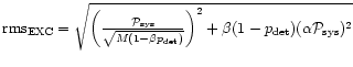
Practically obtainable statistical errors with this method depend on the fitting procedure used to determine the estimate of the power spectrum P(f). There are several approaches to do this: a) to calculate a histogram
![]() or a sample probability distribution of P(f), or b) to sample the statistical moments
or a sample probability distribution of P(f), or b) to sample the statistical moments
![]() .
For the case of histogram fitting, the values at each frequency bin f can be used to make estimates of the system-plus-signal noise rms
.
For the case of histogram fitting, the values at each frequency bin f can be used to make estimates of the system-plus-signal noise rms
![]() ,
and the interference amplitude
,
and the interference amplitude
![]() ,
in order to minimize the residuals, such that:
,
in order to minimize the residuals, such that:
| (38) |
| (39) |
The effectiveness of this method depends also on the temporal stability of INR. Equations (38) and (39) must be solved under the assumption of a constant RFI signal during averaging, so that the total averaging procedure can be divided in the following stages: preliminary averaging - RFI subtraction - final averaging.